집블로그스마트하고 안정적인 크레인 휠 하중 계산: 안전을 구축하고, 성능을 향상시키고, 마음의 평화를 얻으세요
스마트하고 안정적인 크레인 휠 하중 계산: 안전을 구축하고, 성능을 향상시키고, 마음의 평화를 얻으세요
날짜: 2025년 6월 25일
목차
크레인 휠 하중 계산은 크레인 설계 및 선정 과정에서 핵심 단계입니다. 정확한 하중 계산은 크레인의 안전성과 신뢰성에 직접적인 영향을 미칠 뿐만 아니라 장비의 수명 및 유지보수 비용에도 영향을 미칩니다. 실제로 휠 하중은 크레인 자중, 인양된 화물의 무게, 동적 하중, 그리고 환경 요인의 복합적인 영향으로 발생합니다. 따라서 정확한 하중 계산을 위해서는 크레인의 구조적 형태, 작업 조건 및 작동 방식, 그리고 휠이 다양한 작업 조건에서 안전하고 안정적으로 작동할 수 있도록 다양한 요인을 고려해야 합니다.
크레인 휠 하중 계산
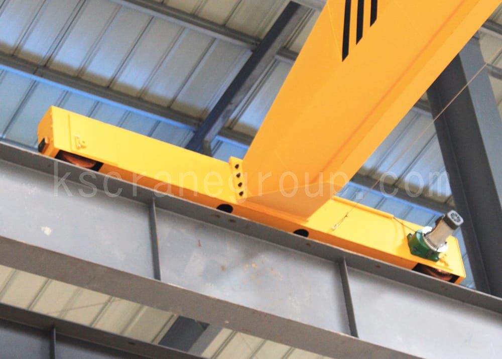
크레인 바퀴가 지탱하는 하중은 주행 장치의 구동 시스템 하중과 아무런 관련이 없으며, 크레인 외부 하중의 평형 조건에 따라 직접 구할 수 있습니다. 오버헤드 주행 크레인의 바퀴 하중에는 최대 바퀴 하중과 최소 바퀴 하중이 포함됩니다. 오버헤드 주행 크레인의 최대 바퀴 하중은 만재된 트롤리가 엔드 거더의 한계 위치에 가까울 때 큰 바퀴의 바퀴 하중이고, 최소 바퀴 하중은 트롤리가 경간 중앙에서 하역될 때 경간 한쪽 끝의 큰 바퀴의 바퀴 하중입니다.
최대 휠 하중(전하중) = (G-G1)/n + (Q+G1)*(L-L1)/n*L
최소 휠 하중(무하중) = (G-G1)/n + G1*L1/n*L
G = 총 크레인 중량(트롤리 포함)(T)
G1 = 트롤리의 무게(T)
Q = 정격 리프팅 용량(T)
L = 범위(m)
n = 크레인의 바퀴 수
L1 = 후크 중심선에서 엔드 빔 중심선까지의 최소 거리(T) 후크 중심선에서 엔드 빔 중심선까지의 최소 거리(m)
크레인 휠 선택 및 검증
크레인 하중에 따른 휠 선택 방법 및 휠이 하중을 견딜 수 있는지 확인하는 방법
1. 휠의 피로 계산 하중 결정:
바퀴의 피로 계산 하중 PC는 크레인의 최대 및 최소 바퀴 압력에 의해 결정될 수 있으며, PC를 계산하는 공식은 다음과 같습니다.
PC — 휠 피로 계산 하중(N);
피최대 — 크레인이 정상적으로 작동할 때의 최대 휠 압력(N)
피분 — 크레인이 정상적으로 작동할 때의 최소 휠 압력(N)
P를 결정할 때최대 그리고 P분, 호이스트 및 작동 장치의 동적 하중 계수와 충격 계수는 1로 간주됩니다.
오버헤드 주행 크레인의 경우 트롤리 크레인이 정격 하중을 한쪽 한계 위치까지 작동할 때 트롤리 측 근처의 큰 휠 압력은 P입니다.최대; 트롤리 쪽에서 멀리 떨어진 무부하 측의 큰 휠 압력은 P입니다.분. 오버헤드 주행 크레인의 경우 트롤리 크레인의 정격 하중이 한쪽 한계 위치까지 주행할 때 트롤리 측 근처 바퀴의 압력은 P입니다.최대; 트롤리 측면으로부터 하중이 제거된 바퀴의 압력은 P입니다.분. 지브 크레인의 경우, 전체 하중의 최대 진폭의 붐 아래 바퀴의 압력은 P입니다.최대; 그리고 무부하 최소 진폭의 붐 아래의 바퀴의 압력은 P이다.분.
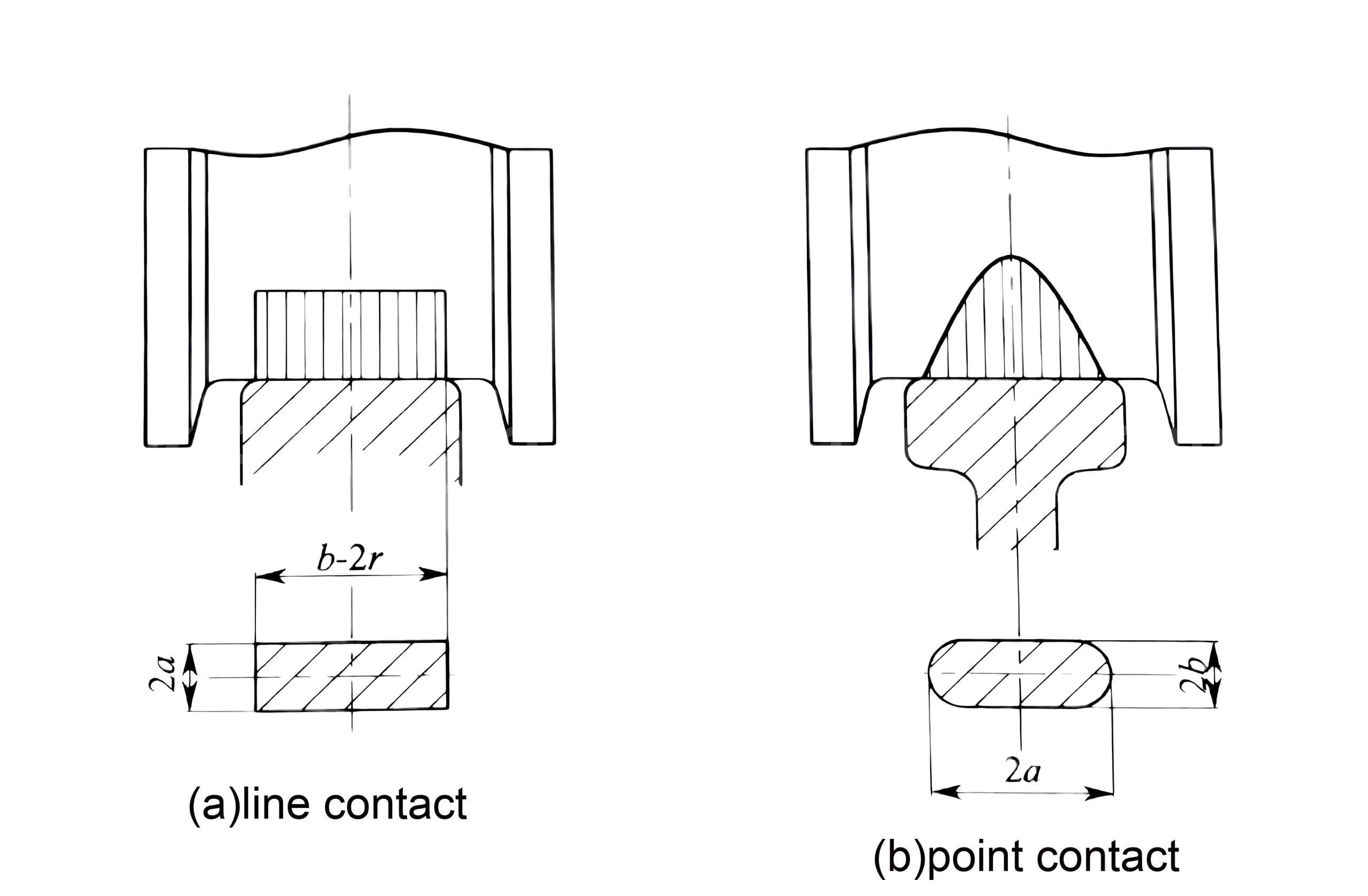
2. 휠 트레드 접촉 강도 계산:
2.1 라인 접촉에 허용되는 휠 압력:
피기음≤케이1×D×L×C1×씨2
피씨 —- 휠 피로 계산 하중(N);
케이1 —– 재료에 관련된 허용 선 접촉 응력 상수(N/mm2)는 표 1에 따라 선정됩니다.
D —– 휠 직경(mm);
L—— 바퀴와 트랙의 유효 접촉 길이.
씨1—– 속도 계수는 표 2에 따라 선정됨.
씨2—– 작업 수준 계수는 표 3에 따라 선택되었습니다.
계산 요소 일정(표 1):
시그마비
케이1
케이2
500
3.8
0.053
600
5.6
0.1
650
6.0
0.132
700
6.8
0.181
800
7.2
0.245
휠 트레드 접촉 강도 계산을 위한 계수 일정 1
메모:
1. σ비 재료의 인장 강도(N/mm2);
2. 강철 휠은 일반적으로 열처리를 해야 하며, 트레드 경도는 HB=300~380, 담금질층 깊이는 15mm~20mm가 권장됩니다. 허용값 결정 시, σ비 재료가 열처리되지 않은 경우에 취해집니다.
3. 휠 재료가 연성 철을 채택하는 경우; σ비.≥500N/mm2 재료, K1, 케이2 값은 σ에 따라 선택됩니다.비.=500N/mm2.
계산 요소 일정(표 2):
RPM
씨1
RPM
씨1
RPM
씨1
분-1
분-1
분-1
200
0.66
50
0.94
16
1.09
160
0.72
45
0.96
14
1.1
125
0.77
40
0.97
12.5
1.11
112
0.79
35.5
0.99
11.2
1.12
100
0.82
31.5
1.00
10
1.13
90
0.84
28
1.02
8
1.14
80
0.87
25
1.03
6.3
1.15
71
0.89
22.4
1.04
5.6
1.16
63
0.91
20
1.06
5
1.17
56
0.92
18
1.07
휠 트레드 접촉 강도 계산을 위한 계수 일정 2
계산 요소 일정(표 3):
운영 조직 실무 수준
씨2
엠1~엠3
1.25
M4
1.12
엠5
1.00
엠6
0.9
M7、M8
0.8
휠 트레드 접촉 강도 계산을 위한 계수 일정 3
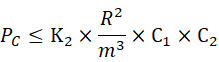
2.2 점 접촉에 대한 허용 휠 압력:
피씨 —- 휠 피로 계산 하중(N);
케이2 —– 재료 관련 허용 접촉점 응력 상수(N/mm2)는 표 1에 따라 선택됩니다.
R —– 곡률 반경, 바퀴의 곡률 반경과 궤도의 곡률 반경 중 더 큰 값(mm)을 취합니다.
위의 계산은 바퀴의 유효 최대 하중 지지 용량과 치수의 합리성(바퀴 직경, 바퀴 치수 및 트랙 맞춤 등)을 결정하기 위해 설정된 직경을 가진 바퀴의 검증을 검증하는 데 사용될 수 있습니다.
대형 차량 휠 세트에 대한 최대 허용 휠 압력 표:
휠 직경/mm
철도 모형
작업 수준
주행 속도/(m/분)
질문/답변
<60
60~90
90~180
1.1
0.5
0.15
1.1
0.5
0.15
1.1
0.5
0.15
500
P38
엠1~엠3
20.6
19.7
18
18.7
17.9
16.4
17.2
16.4
15
M4、M5
17.2
16.4
15
15.6
15
13.7
14.4
13.7
12.5
M6、M7
14.7
14.1
12.9
13.4
12.8
11.7
12.3
11.7
10.7
엠8
12.9
12.3
11.3
11.7
11.2
10.3
10.7
10.3
9.4
QU70
엠1~엠3
26
24.3
22.7
23.6
22.6
20.6
21.7
20.7
19
M4、M5
21.7
20.7
19
19.7
18.9
17.2
18.1
17.3
15.9
M6、M7
18.6
17.7
16.2
16.9
16.2
14.7
15.5
14.8
13.6
엠8
16.3
15.5
14.2
14.8
14.1
12.9
13.6
12.9
11.6
600
P38P43
엠1~엠3
24.6
23.5
21.5
22.4
21.4
19.5
20.6
19.6
18
M4、M5
20.6
19.6
18
19.7
17.8
16.3
17.2
16.4
15
M6、M7
17.6
16.8
15.4
16
15.3
14
14.7
14
12.9
엠8
15.4
14.7
13.4
14
13.4
12.2
12.9
12.3
11.3
QU70
엠1~엠3
32
30.5
27.9
29.2
27.8
25.4
26.7
25.5
23.3
M4、M5
26.7
25.5
23.3
24.4
23.2
21.2
22.3
21.3
19.4
M6、M7
22.9
21.8
19.9
20.9
19.9
18.1
19.1
18.2
16.7
엠8
20
19.1
17.4
18.3
17.4
15.8
16.7
15.9
14.0
700
P43
엠1~엠3
28
26.8
24.5
25.5
24.4
22.3
23.4
22.4
20.4
M4、M5
23.4
22.4
20.4
21.3
20.4
18.6
19.5
18.7
17
M6、M7
20
19.2
17.5
18.3
17.4
15.9
16.7
16
14.6
엠8
17.5
16.7
15.3
15.9
15.2
13.9
14.6
14
12.7
QU70
엠1~엠3
38.6
36.8
33.6
35.2
33.5
30.6
32.2
30.7
28
M4、M5
32.2
30.726
28
29.4
28
25.6
26.9
25.6
23.4
M6、M7
27.6
3
24
25.2
24
21.9
23
22
20
엠8
24.2
23
21
22
21
19.1
20.1
19.2
17.5
800
QU70
엠1~엠3
43.7
41.7
38.1
39.8
38
34.7
36.4
34.8
31.8
M4、M5
36.4
34.8
31.8
33.2
31.7
29
30.4
29
26.6
M6、M7
31.2
29.8
27.2
28.4
27.2
24.8
26
24.9
22.7
엠8
27.3
26.1
23.8
24.9
23.8
21.7
22.8
21.8
19.8
900
QU80
엠1~엠3
50.5
48.1
44
46
43.7
40
42.2
40.2
36.8
M4、M5
42.4
40.2
36.8
38.4
36.5
33.4
35.2
33.6
30.7
M6、M7
36.1
34.4
31.5
32.9
31.2
28.6
30.2
28.8
26.3
엠8
31.6
30.1
27.5
28.8
27.3
25
26.4
25.1
23
대형 차량 휠 세트에 대한 최대 허용 휠 압력 표
트롤리 휠 세트에 대한 최대 허용 휠 압력 표:
휠 직경/mm
철도 모형
작업 수준
주행 속도/(m/분)
질문/답변
<60
60~90
90~180
180개
≥1.6
0.9
≥1.6
0.9
≥1.6
0.9
≥1.6
0.9
250
P11
엠1~엠3
3.3
3.09
2.91
2.81
2.67
2.58
2.46
2.34
M4、M5
2.67
2.58
2.43
2.34
2.23
2.15
2.5
1.98
M6、M7
2.38
2.51
2.08
2.01
1.91
1.84
1.76
1.7
엠8
2
1.93
1.82
1.76
1.67
1.61
1.54
1.48
350
P18
엠1~엠3
4.18
4.03
3.8
3.66
3.49
3.36
3.22
3.1
M4、M5
3.49
3.36
3.17
3.06
2.91
2.8
2.68
2.59
M6、M7
2.99
2.88
2.72
2.62
2.5
2.4
3.2
2.22
엠8
2.61
2.52
2.38
2.29
2.18
2.1
2.01
1.94
P24
엠1~엠3
14.1
13.5
12.8
12.3
11.8
11.3
10.9
10.4
M4、M5
11.8
11.3
10.7
10.3
9.85
9.45
9.1
8.7
M6、M7
10.1
9.65
9.15
8.8
8.45
8.1
7.8
7.45
엠8
8.8
8.45
8
7.7
7.4
7.06
6.8
6.5
400
P38
엠1~엠3
16
15.4
14.6
14
13.4
12.8
12.3
11.85
M4、M5
13.4
15.8
12.2
11.7
11.2
10.7
10.3
9.9
M6、M7
11.4
11
10.4
10
9.6
9.15
8.8
8.5
엠8
10
9.6
9.15
8.75
8.4
8
7.7
7.4
500
P43
엠1~엠3
19.8
19.1
18
17.4
16.5
15.9
15.2
14.7
M4、M5
16.5
15.9
15
14.5
13.8
13.3
12.7
12.25
M6、M7
14.15
13.7
12.9
12.45
11.8
11.4
10.9
10.5
엠8
12.4
11.9
11.25
10.9
10.3
9.95
9.5
9.2
트롤리 휠 세트에 대한 최대 허용 휠 압력 표
참고: 이 표의 값은 휠 소재 ZG310-570, HB320에 따라 계산되었습니다. 휠 소재가 ZG50MnMo이고 휠 축이 45, HB = 228 ~ 255인 경우 최대 허용 휠 압력은 20%만큼 증가할 수 있습니다.
Q – 크레인 리프팅 용량
G — 크레인 자체중량.
크레인 휠 하중 계산은 크레인의 안전, 안정성 및 내구성을 보장하는 기본 작업입니다. 휠 하중을 정확하게 계산하면 크레인 설계를 최적화하고, 적절한 재료와 제조 공정을 선택하여 장비의 전반적인 성능을 향상시킬 수 있습니다. 크레인 휠 하중 계산은 복잡하지만 필수적인 프로젝트로, 엄격한 분석과 계산을 통해 구현되어야 합니다.
표준을 충족하지 못하는 크레인 휠의 숨겨진 위험
기준을 충족하지 못하는 크레인 휠은 장비의 성능, 안전성 및 장기적인 사용에 심각한 영향을 미치며, 이는 다음과 같은 측면에서 나타납니다.
1. 안전 위험 증가
휠 파손 또는 고장: 휠 재질이 기준을 충족하지 못하면 크레인의 정상 하중을 견디지 못하고 파손이나 심각한 마모가 발생하기 쉽습니다. 이는 작업자의 안전에 직접적인 위협이 되며, 특히 고하중이나 고속 작업의 경우 사고로 이어질 수 있습니다.
궤도 변형 또는 탈선: 기준에 맞지 않는 바퀴는 바퀴와 궤도 사이의 접촉 불량으로 이어져 크레인이 변형되거나 탈선하여 사고 위험이 커집니다.
2. 마모 및 손상 증가
불균일 마모: 휠의 품질이 기준에 미치지 못하면 경도나 구조가 고르지 않은 등 휠 표면에 결함이 발생하여 불균일 마모가 발생할 수 있습니다. 이러한 불균일 마모는 휠과 트랙의 손상을 가속화하고 유지 보수 비용을 증가시킵니다.
과도한 마모: 품질이 좋지 않은 바퀴는 장기간 사용하면 너무 빨리 마모되어 바퀴 치수가 변하고 크레인의 안정성과 작동 정확도에 영향을 미칠 수 있습니다.
3. 운영 성과에 영향을 미치는
불균형 및 진동: 품질이 좋지 않은 휠은 크레인 작동을 고르지 않게 만들어 과도한 진동과 소음을 발생시키고, 작업 효율과 편의성에 영향을 미칠 수 있습니다. 장기간 진동은 다른 기계 부품(예: 베어링, 모터 등)의 손상을 초래할 수도 있습니다.
불균일한 하중 분포: 휠 품질 문제는 특히 여러 개의 휠 구성을 가진 크레인의 경우 하중 분포 불균일로 이어질 수 있습니다. 이는 장비의 하중 용량과 작업 효율에 영향을 미쳐 크레인의 효율적이고 안정적인 작동을 저해합니다.
4. 장비 수명 단축
조기 노화 및 고장: 품질이 좋지 않은 휠 소재 및 구조는 피로, 부식 및 기타 손상에 더 취약하게 만들어 크레인의 전체 수명을 단축시킬 수 있습니다. 따라서 휠 교체 빈도가 증가하여 추가적인 유지보수 비용이 발생합니다.
다른 구성 요소의 마모가 가속화됩니다. 품질이 좋지 않은 바퀴는 다른 중요한 크레인 구성 요소(예: 구동 시스템, 레일 시스템, 후크 등)의 조기 마모로 이어져 유지 관리의 어려움과 비용이 증가합니다.
5. 유지관리 및 운영 비용 증가
잦은 수리: 기준에 맞지 않는 휠을 사용하면 장비에 더 자주 수리, 교체 또는 교정이 필요하게 됩니다. 이는 운영 비용을 증가시킬 뿐만 아니라 장비 가동 중지 시간이 늘어나 생산성에 영향을 미칠 수 있습니다.
조기 교체: 품질이 낮은 휠은 장기간 높은 하중 수요를 감당하지 못할 수 있으므로 조기 교체가 필요하고 유지 관리 비용과 부품 교체 비용이 증가합니다.
6. 전체 시스템 안정성에 미치는 영향
변속 시스템의 손상: 바퀴의 품질 문제는 변속 시스템의 비정상적인 작동으로 이어질 수 있습니다. 예를 들어, 모터, 감속기 및 기타 구성 요소의 조기 마모 또는 손상으로 인해 전체 크레인 시스템의 안정성과 작동성에 영향을 미칠 수 있습니다.
궤도 시스템 손상: 기준 미달의 바퀴가 궤도 시스템에 충격을 주면 궤도가 손상되거나 변형될 수 있으며, 이는 장비의 안정성에 영향을 미치고 더 빈번한 궤도 수리 및 교체가 필요할 수 있습니다.
예방 조치:
엄격한 품질 관리: 휠 소재와 생산 공정이 업계 표준을 준수하는지 확인하고, 신뢰할 수 있는 품질 공급업체를 선택하고, 세부적인 검사와 테스트를 실시합니다.
정기 검사 및 유지관리: 크레인 바퀴를 정기적으로 검사하여 잠재적인 마모와 균열을 감지하고 필요한 유지관리 및 교체를 실시합니다.
합리적인 설계 및 선택: 크레인의 작업 조건에 따라 적절한 사양의 바퀴를 선택하여 예상되는 하중과 작업 환경을 견딜 수 있는지 확인하세요.
크리스탈
크레인 OEM 전문가
8년간의 리프팅 장비 맞춤 제작 경험을 바탕으로 10,000명이 넘는 고객의 사전 판매 질문과 우려 사항을 해결해 드렸습니다. 관련 요구 사항이 있으면 언제든지 저에게 연락해 주세요!


.png?w=200&h=134)