- EQUIPMENT
- special cranes
-
Industry Crane
-

Industry Crane
-

Tundish Cranes
-

Slab Cranes
-

Scrap Cranes
-

Billet Cranes
-

Coil,Bar and Plate Handling Cranes
-

Cement And Precast Crane
-

Power Station Crane
-

Ladle Cranes
-

Paper Industry Cranes
-

Waste to Energy Cranes and Biomass Cranes
-

Tailored Overhead Cranes for Aerospace: High Precision, Efficience, Safety and Reliability
-
-
Hoist & Winch Trolley
-

Casting Electric Wire Rope Hoist
-

European Model Electric Hoist
-

Explosion-proof Electric Hoist
-

Low-headroom Electric Hoist
-

Electric Chain Hoist
-

2 Types Explosion-Proof Electric Chain Hoists for Hazardous Zones: Gas & Dust Protection
-

2 Types Explosion-Proof Electric Wire Rope Hoists for Industrial Safety: Reliable Gas & Dust-Proof Solutions
-
-
CRANE Spreader
-
Crane Electromagnetic Lifting Magnets
-

Lifting Electromagnet for Turning and Side Hung
-

Lifting Electromagnet for Thick Plate
-

Specialized Electromagnet for Lifting Steel Plates
-

Lifting Electromagnets for Lifting Steel Plates
-

Lifting Electromagnet for Heavy Rail and Profiled Steel
-

Lifting Electromagnet for High Speed Wier(Coiled Bar)
-

Lifting Electromagnet for Rebar and Steel Pipe
-

Lifting Electromagnet for Bundled Rebar and Profiled Steel
-

Lifting Electromagnet for Billet, Girder Billet and Slab
-

Lifting Electromagnet for Steel Scraps
-
- Crane Spreader
- Crane Lifting Tongs and Clamps
-
Crane Electromagnetic Lifting Magnets
- CRANE PARTS
- Transfer Cart

Application for Different Types of Foundry Cranes in Real Projects
31 May, 2024

Foundry cranes lift liquid metal in a harsh environment of high temperatures and high dust, and are frequently used and work at high levels.
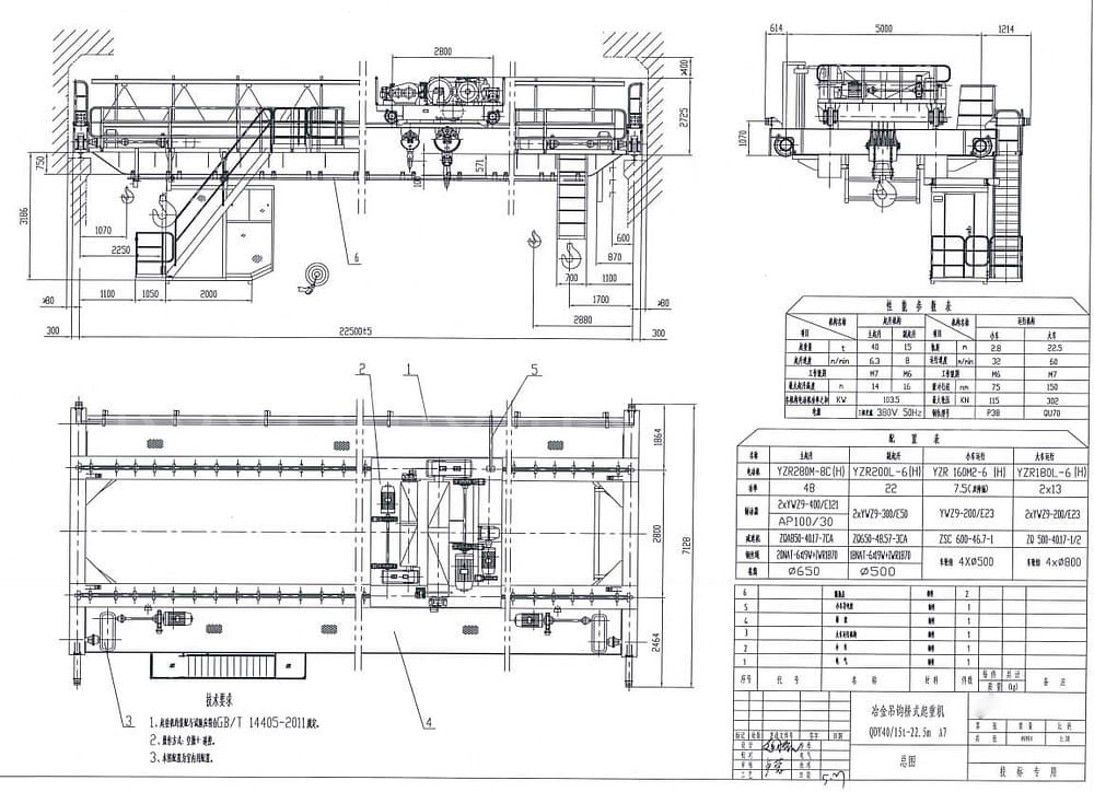
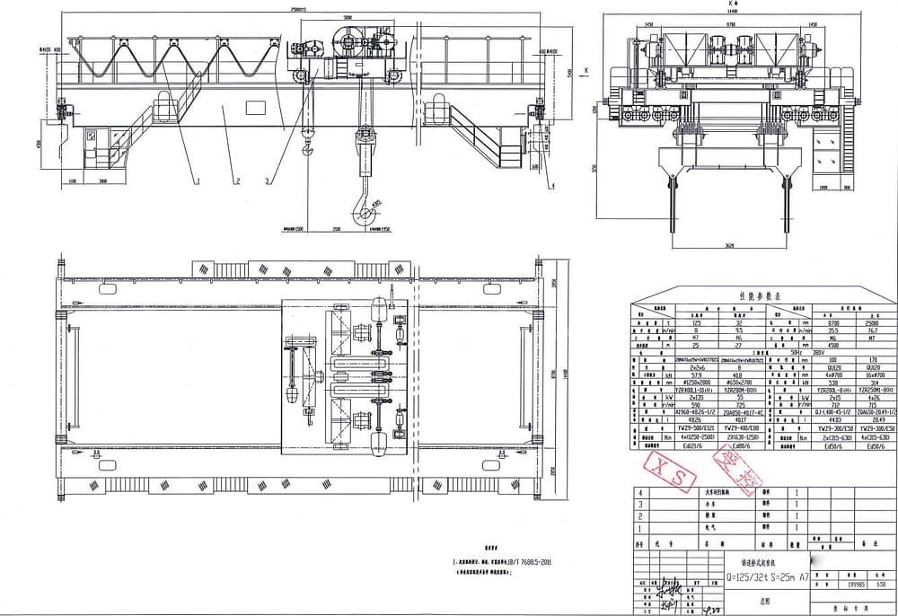
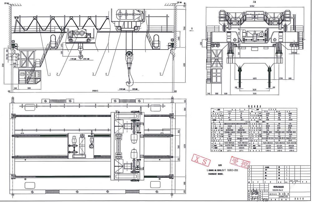
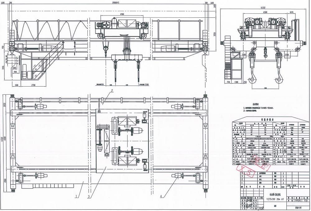
Types of foundry crane
 |
 |
 |
|---|---|---|
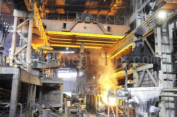
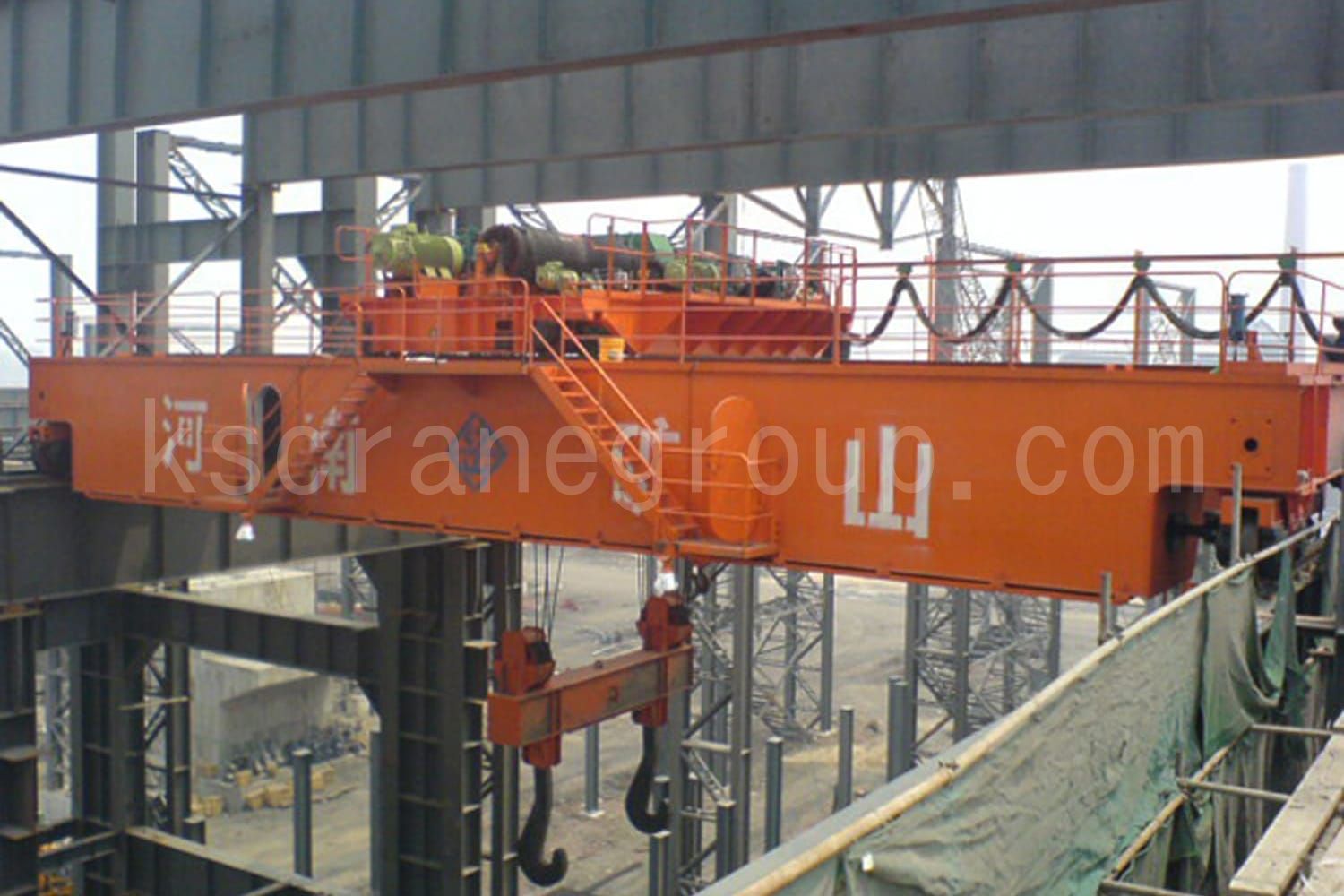
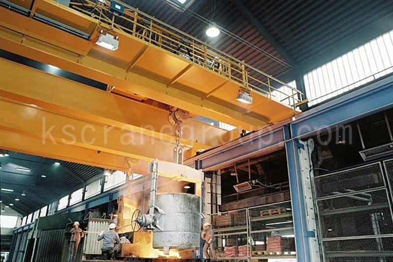
| YZS Four Beam Foundry Crane | YZ Double Girder Foundry Crane | YZ Hook type Foundry Crane |
Project Cases
40Ton YZ double girder foundry crane used for casting workshop of ferrosilicon furnace project
| Lifting mechanism | Operational organization | ||||||
|---|---|---|---|---|---|---|---|
| Main | Auxiliary | Trolley | Crane | ||||
| Lifting weight | t | 40 | 15 | Track distance | m | 2.8 | 22.5 |
| Lifting speed | m/min | 6.3 | 8 | Travelling speed | m/min | 32 | 60 |
| Working class | M7 | M6 | Working class | M6 | M7 | ||
| Max. lifting height | m | 14 | 16 | Buffer stroke | mm | 75 | 150 |
| Sum of power | KW | 103.5 | Max wheel load | KN | 115 | 302 | |
| Power source | 3-phase AC 380V 50Hz | Rail type | P38 | QU70 | |||
Structural characteristics
- This equipment adopts the structural type of double girder and double rail, and single trolley for winch.
- The crane winch trolley is equipped with main and vice hoisting mechanism, each adopting a set of independent transmission system. The main and vice hoisting mechanism can not only complete the lifting independently, but also cooperate to complete the work of turning over the equipment.
- The working principle of the hoisting mechanism: the hoisting motor does the work, changes the speed through the speed reducer, and then drives the reel through the reel coupling or C-type gear disk, and completes the lifting and lowering of the hook through the wire rope winding system.
- The running mechanism of the crane adopts 1/2 drive structure type, with smooth starting and braking and no slipping phenomenon.
- The running mechanism of the trolley adopts the scheme of driving wheels at two angles. Driven by the motor, the power is transferred to the reducer through the gear coupling and transmission shaft, and after deceleration by the reducer, the active wheels are driven through the transmission shaft and gear coupling to drag the whole vehicle and complete the longitudinal movement. The end of the wheels are equipped with rail cleaner, so as to automatically remove the obstacles on the track surface when the crane is traveling, to ensure the safety of the crane traveling.
- The main and secondary hoisting mechanism are arranged on the same frame, with independent driving device. The driving device of the main and vice hoisting mechanism is compact and easy to maintain to ensure safety and reliability.
- The hoisting mechanism consists of electric motor, coupling, brake, reducer, reel, pulley group, hook group, wire rope and other components. It is driven by a single motor, and after decelerated by the reducer, it drives the duplex reel and lifts the hook through the wire rope winding system composed of the fixed pulley and the dynamic pulley group.
- The trolley running mechanism adopts the scheme of centralized driving two wheels. Driven by the motor, the power is transferred to the reducer through gear coupling and transmission shaft, and after decelerated by the reducer, the active wheels are driven through the transmission shaft and gear coupling to drag the trolley and complete the transverse movement. The end of the wheels are equipped with rail cleaner, so that the crane travels automatically clear the obstacles on the track surface to ensure the safety of the crane traveling.
Safety devices
- Overload limiter is installed in both main and assistant hoisting mechanism of the crane. When the load reaches 90% of the rated lifting capacity, a prompt alarm signal is issued; when the lifting capacity exceeds 105% of the rated lifting capacity (adjustable); when the lifting capacity exceeds 110% of the rated lifting capacity, the power supply of the lifting power can be cut off automatically and a prohibitive alarm signal is issued. There is a real-time lifting weight digital display in the traveling crane operation room.
- In accordance with the safety regulations of crane machinery, each exposed rotating parts with the risk of injury to set the protective cover, and wire rope anti-skipping device. The form of protective cover is detachable safety cover.
- The crane is equipped with lifting height limiter and running stroke limiter to realize the safety protection of movement stroke and working position through electrical control.
- Buffers and other buffer devices are installed on the crane to buffer the inertial kinetic energy of the crane running brake. At the same time in the crane limit position of each operating mechanism to install stopping devices to prevent the crane running over the limit position of the danger.
- The crane is equipped with a rail sweeping device to clean up the debris on the running track to prevent the crane from derailing and other dangers caused by debris on the track.
- Electrical interlocking protection system is installed at the crane railing door and end beam to cut off the power supply of the organization that causes danger to the personnel due to the operation of the organization.
- The electrical part of the crane is equipped with phase shortage protection, wrong phase protection, zero protection, under-voltage and over-voltage protection, short-circuit protection, over-current protection, grounding protection and other electrical protections to ensure that the crane can work stably in a safe condition.
125Ton YZ double girder foundry crane used for lifting steel to continuous casting rotary ladle table across the steel mill steel span

| Lifting mechanism | Operational organization | ||||||
|---|---|---|---|---|---|---|---|
| Main | Auxiliary | Trolley | Crane | ||||
| Lifting weight | t | 125 | 32 | Track distance | mm | 8700 | 25000 |
| Lifting speed | m/min | 8 | 9.5 | Travelling speed | m/min | 35.5 | 76.7 |
| Working class | M7 | M6 | Working class | M6 | M7 | ||
| Max. lifting height | m | 25 | 27 | basal distance | mm | 4500 | |
| Power source | 3-phase AC 380V 50Hz | ||||||
Crane characteristics
- This equipment adopts the structure type of double girder, double rail and single trolley.
- The bridge adopts wide flange offset rail box structure, and the main girder adopts “T” steel structure for the connection between the main web and the pressurized flange plate, which has good rigidity and strength, stability and strong fatigue resistance. The internal space of the main beam is large and closed, which is convenient for the installation and maintenance of the running mechanism and electric control equipment as well as dust protection.
- The end girder adopts box-type structure, and the whole one is processed and produced, which is convenient for transportation.
- The end girder and the main girder are connected rigidly (bolt group connection) or articulated according to the structural form of the bridge.
- The driver’s room adopts closed heat preservation type, tempered glass, comfortable and adjustable seats with good vision, and is installed with cold and warm air-conditioning.
- The running mechanism of the trolley adopts four-corner separate drive program, and the reducer, motor and brake of the running mechanism are installed in the closed main beam, which meets the requirements of the harsh working environment of high temperature and high dust of the casting crane. The trolley set is installed at the end of the main beam, which is easy to dismantle and install.
- The main hoisting mechanism adopts the scheme of two sets of drive and four wire ropes winding. Two motors drive two sets of duplex reel units through two speed reducers. At this time, the two reels are arranged in series, and the wire rope on the reel device, the fixed pulley set, the balance arm and the lifting beam (gantry hook) form a four wire rope winding system.
- Two brakes are installed at the input shaft end of each driving device, and the braking safety factor of each brake is not less than 1.1 times, therefore, even if the gear shaft in any one of the reducer breaks, the hoisting mechanism can still ensure that the lifted objects will not fall.
- The two sets of reeling devices are rigidly connected through the drum-type tooth coupling to achieve the synchronization purpose, that is, to ensure the synchronization of the work of the two sets of reeling devices, but also to ensure the safety of the work of any one of the two gear reducers in the gear or the gear shaft breakage.
- The main hoisting mechanism has two sets of driving system, when one set of driving system fails, the other set of driving system should be able to ensure that the rated lifting capacity to complete a work cycle.
- The four wire rope winding system has mutual independence between the four wire ropes, the main hoisting mechanism with four wire rope winding system, when a wire rope or diagonal two wire rope breakage can still put the weight on the ground.
- The main hoisting mechanism is used to complete the lifting of molten metal.
- The secondary hoisting mechanism adopts a single drive scheme. An electric motor drives a set of duplex reel device through a reducer to realize the lifting and lowering function of the hook set through the wire rope winding system.
- The secondary hoisting mechanism is used for dumping molten metal or lifting small objects.
- The reducer of the hoisting mechanism adopts medium hardened gear reducer.
- Special motor for metallurgical lifting is adopted. When the environment exceeds 40℃, the motor should be insulated with H-class insulation, and the motor should have good sealing and the protection level is IP54.
- The electrical room is set inside the main beam, insulated and closed, with industrial chillers for cooling to ensure that the indoor temperature is not greater than 35 ℃, the walkway floor should be paved with non-conductive rubber sheets, air-conditioning condensate centralized discharge.
125Ton YZS Four beam foundry for lifting molten iron to the refining furnace across the refining span in steel mills

| Lifting mechanism | Operational organization | |||||||
|---|---|---|---|---|---|---|---|---|
| Main | Auxiliary | Main Trolley | Auxiliary Trolley | Crane | ||||
| Lifting weight | t | 125 | 32 | Track distance | mm | 11220 | 3000 | 19000 |
| Lifting speed | m/min | 7 | 12 | Travelling speed | m/min | 34.8 | 42.2 | 76.7 |
| Working class | M7 | M6 | Working class | M6 | M6 | M7 | ||
| Max. lifting height | m | 20.5 | 22.5 | basal distance | mm | 2500 | 1750 | 12220 |
| Power source | 3-phase AC 380V 50Hz | |||||||
Crane characteristics
- This equipment adopts the structure type of four girders, four rails and two trolleys.
- The bridge adopts wide flange offset rail box structure, and the main girder adopts “T” steel structure for the connection between the main web and the pressurized flange plate, which has good rigidity and strength, stability and strong fatigue resistance. The internal space of the main beam is large and closed, which is convenient for the installation and maintenance of the running mechanism and electric control equipment as well as dust protection.
- The end girder adopts box-type structure, and the whole girder is processed and produced, which is convenient for transportation.
- The end girder and the main girder are connected rigidly (bolt group connection) or articulated according to the structural form of the bridge.
- The driver’s room adopts closed heat preservation type, tempered glass, comfortable and adjustable seats with good vision, and is installed with cold and warm air-conditioning.
- The running mechanism of the trolley adopts four-corner separate drive program, and the reducer, motor and brake of the running mechanism are installed in the closed main beam, which meets the requirements of the harsh working environment of high temperature and high dust of the casting crane. The trolley set is installed at the end of the main beam, which is easy to dismantle and install.
- The hoisting mechanism adopts the scheme of two sets of drive and four wire ropes winding. Two motors drive two sets of duplex reel units through two speed reducers. (The reels are arranged in series for (100-160t) and in parallel for (180-320t). The wire rope, fixed pulley set, counterbalance arm and lifting girder (gantry hook) on the drum unit form a four wire rope winding system.
- Two brakes are installed at the input shaft end of each drive unit, and the braking safety factor of each brake is not less than 1.1 times, so that even if the gear shaft in any one of the reduction gears breaks, the hoisting mechanism can still ensure that the lifted objects will not fall.
- Depending on the rated lifting capacity, the lifting mechanism can be a double reduction model, an overall large reduction model or a planetary triple reduction model.
- When the lifting mechanism adopts double reduction model, the two sets of reel devices or two reducers are rigidly connected through the drum-type tooth coupling to achieve synchronization, which ensures that after the failure of one motor, the other motor can drive the whole lifting mechanism to complete a working cycle through the two sets of reel devices or the two reducers’ rigidly connected devices.
- When the lifting mechanism adopts the overall large reduction model, the gears in the large reduction gear in the low-speed axis will chain the two sets of mechanisms to achieve the purpose of synchronization, which ensures that after the failure of one motor, the other motor can be synchronized through the large reduction gear in the low-speed axis to drive the entire lifting mechanism to complete a work cycle.
- When the lifting mechanism adopts planetary triple reduction model, the planetary reducer has double degree of freedom characteristic, when the motor on one of the two input shafts of the planetary reducer fails, the working brake on the shaft holds the brake, and the motor on the other upper shaft can run steadily alone and make the whole mechanism work for a long period of time at half of the rated speed.
- The four wire ropes in the wire rope winding system are independent of each other, and can still place heavy loads on the ground when one rope or two diagonal ropes break.
- The main trolley is used to complete the lifting of molten metal.
- The secondary trolley consists of lifting mechanism, trolley running mechanism and trolley frame.
- The lifting mechanism adopts a single drive scheme. An electric motor drives a set of duplex reels through a speed reducer to realize the lifting and lowering function of the hook set through the wire rope winding system.
- The secondary trolley is used to complete the work of dumping molten metal or lifting small articles.
- The reducer of the hoisting mechanism adopts medium hardened gear reducer.
- Special motor for metallurgical lifting is adopted. When the environment exceeds 40℃, the motor should be insulated with H-class insulation, and the motor should have good sealing and the protection level is IP54.
- The electrical room is set inside the main beam, insulated and closed, with industrial chillers for cooling to ensure that the indoor temperature is not greater than 35 ℃, the walkway floor should be paved with non-conductive rubber sheets, air-conditioning condensate centralized discharge.
75Ton YZ double girder four lifting point foundry crane for steelmaking workshop in iron and steel factory

| Lifting mechanism | Operational organization | ||||||
|---|---|---|---|---|---|---|---|
| Main | Auxiliary | Trolley | Crane | ||||
| Lifting weight | t | 75 | 20 | Track distance | mm | 6500 | 28000 |
| Lifting speed | m/min | 6.5 | 9.3 | Travelling speed | m/min | 40.6 | 67 |
| Working class | M7 | M6 | Working class | M6 | M7 | ||
| Max. lifting height | m | 22 | 24 | basal distance | mm | 4900 | |
| Power source | 3-phase AC 380V 50Hz | ||||||
| Price | CNY755000 | ||||||
Crane characteristics
- This equipment adopts the structure type of double girder and double rail, winch single trolley.
- The crane winch trolley is equipped with main and vice hoisting mechanism, each of which adopts a set of independent transmission system. The main and vice hoisting mechanism can not only complete lifting independently, but also work together to complete the work of turning equipment.
- The running mechanism of the crane adopts 1/2 drive structure type, with smooth starting and braking and no slipping phenomenon.
- The bridge is in the form of double girder and double rail structure, which is composed of main girder, end girder, walking platform, railing, ladder and other subsidiary metal structures.
- The main girder is a positive track box structure, and the bottom is equipped with heat insulation device.
- The cross-section of the main girder adopts ANSYS finite element calculation method to carry out systematic analysis and calculation to ensure that it has sufficient strength, rigidity and overall stability, and reasonably arranges the running mechanism of the large vehicle and electrical equipment on the platform to ensure that the personnel can pass conveniently on the platform.
- The railings with a height of 1050mm, horizontal crossbars with a spacing of 350mm, and enclosure boards with a height of 70mm at the bottom are set up on the main beams, end beams of the bridge and the access to the driver’s room, and assembled in the factory. The railings are capable of withstanding a load of 1kN (100kgf) in any direction without plastic deformation at any point.
- The carriage running mechanism utilizes a two-corner drive wheel solution. Driven by an electric motor, the power is transmitted to the reducer through the gear coupling and transmission shaft. After deceleration by the reducer, the active wheels are then driven through the transmission shaft and gear coupling to drag the whole vehicle and complete the longitudinal movement. The end of the wheels are equipped with rail cleaner, so as to automatically remove the obstacles on the track surface when the crane is traveling, to ensure the safety of the crane traveling.
- The main and secondary hoisting mechanism are arranged on the same frame, with independent driving device. The driving device of the main and vice hoisting mechanism is compact and easy to maintain to ensure safety and reliability.
- The trolley running mechanism adopts the scheme of centralized driving two wheels. The end of the wheels are equipped with rail cleaner, so that when the crane walks, it automatically clears the obstacles on the track surface to ensure the safety of the crane walking.
- The hoisting mechanism is equipped with two sets of independent brakes.
- The reducer of the hoisting mechanism adopts medium hardened gear reducer.
- Adopt special motor for metallurgical lifting, when the environment is more than 40℃, use H class insulated motor, the motor has good sealing, protection grade IP54.
- In order to facilitate the assembly in the manufacturing plant, the transportation process of loading and unloading and the site of the installation of lifting, in the main components are set up for lifting lugs, lifting holes and so on. For example, four lifting lugs are set on the main beam, trolley frame, spreader beam and other upper planes. The strength and location of these lugs and holes are fully considered for the safety and convenience of lifting.
Foundry environment
Cranes in the foundry industry are often used in special environments, the operating environment of the crane in the metallurgical industry is mainly characterized by the following:- Dusty workplace, smelting, casting, heat treatment and other processes can hardly be avoided will produce high-temperature dust, which floats in the air, will be attached to the various surfaces of the crane, and even affect the normal operation of electrical equipment, so the need for specialized metallurgical cranes.
- Higher ambient temperatures, the temperature of molten metal is usually more than 1500 degrees Celsius degrees, the average room temperature in the plant can reach 40-60 degrees Celsius, the molten metal on the spreader’s radiation temperature can reach up to 300 degrees Celsius.
- Air humidity, air will be mixed with corrosive gases, smelting, casting, heat treatment process, will produce some water vapor, but also produce some corrosive gases, resulting in high humidity and high corrosive air environment, this environment will accelerate the corrosion of the metal structure, the crane is very harmful.
Kuangshan Foundry overhead cranes features:
- Driver’s room, electrical room are fully insulated structure, and the room is equipped with cooling equipment (mostly industrial chillers) to ensure the normal operation of the operator and electrical equipment.
- The wire rope adopts high temperature resistant steel core wire rope (metal strand core or metal rope core).
- The hook group or the pulley group on the spreader and the fixed pulley group on the trolley are all fully closed structure to adapt to the operation under high dust environment, effectively extend the service life of the parts and reduce the after-sales rate.
- The hoisting drum is welded drum.
- Pulleys are rolled pulleys.
- Electrical cables are high temperature resistant cables.
- For large metallurgical cranes, if the motor capacity of the single-agency drag is more than 400KW, or the total capacity is more than 500KW, it is recommended to use 50HZ, 3000V power supply.
- 125 tons or more of large car running mechanism and the main electrical equipment are installed in the main beam
Safety measures for Kuangshan Foundry overhead cranes:
- The main purpose of this equipment is to transport molten liquid metal, the working level is high, and the equipment safety requirements are extremely high.
- The working environment conditions are harsh, with high temperature, high dust and harmful gases. The heat insulation layer is set at the bottom of the main beam to prevent the high temperature radiation from adversely affecting the strength of the main beam, which may cause safety hazards.
- And the main hoisting mechanism motor is equipped with an overspeed switch to ensure that the hoisting mechanism in the state of failure of the reel end of the safety brake fast brake.
- Two brakes are provided at both ends of the high-speed shaft of the hoist reducer, and a safety clamp disk brake is provided at one end of the reel to prevent the hook from stalling and slipping.
- When the main hoisting mechanism adopts two sets of driving devices, when one of the motors or one set of electronic control device fails, the other set of driving devices should be able to ensure that the rated lifting capacity to complete a work cycle.
Do you like what we do?Share it


