HomeBlogSmart and Reliable Crane Wheel Load Calculation: Build Safety, Boost Performance, and Win Peace of Mind
Smart and Reliable Crane Wheel Load Calculation: Build Safety, Boost Performance, and Win Peace of Mind
Date: 25 Jun, 2025
Table of Contents
Crane wheel load calculation is a key step in the crane design and selection process. Accurate load calculation not only directly affects the safety and reliability of the crane, but also relates to the service life of the equipment and maintenance costs. In practice, the wheel load is generated by the combined effects of the crane’s self-weight, the weight of the lifted cargo, dynamic loads and environmental factors. Therefore, to carry out accurate load calculation, it is necessary to take into account the structural form of the crane, working conditions and operating mode and other factors to ensure that the wheels can operate safely and stably under various working conditions.
Calculation of Crane Wheel Load Calculation
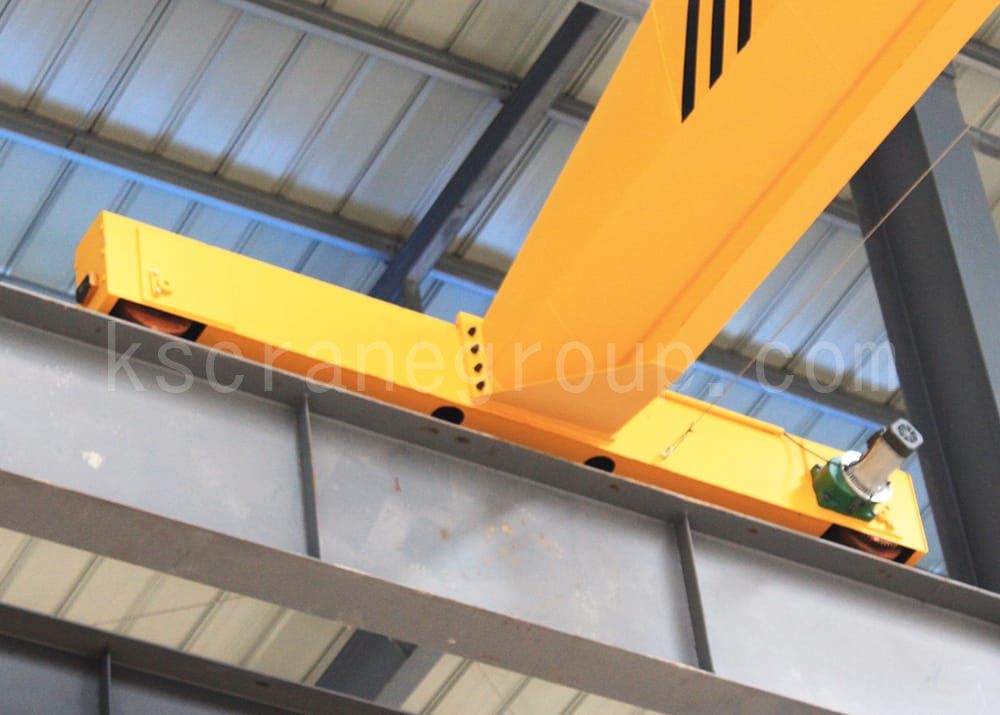
The load borne by the wheels of the crane has nothing to do with the load of the drive system of the running mechanism, and it can be obtained directly according to the equilibrium conditions of the external load of the crane. The wheel load of overhead travelling crane includes the maximum wheel load and minimum wheel load. The maximum wheel load of overhead travelling crane is the wheel load of the big wheel when the fully loaded trolley is close to the limit position of the end girder, and the minimum wheel load is the wheel load of the big wheel of the big wheel of one end of the span when the trolley is unloaded in the middle of the span.
Maximum wheel load (full load) = (G-G1)/n + (Q+G1)*(L-L1)/n*L
Minimum wheel load (no load) = (G-G1)/n + G1*L1/n*L
G = total crane weight (including trolley) (T)
G1 = weight of trolley (T)
Q = rated lifting capacity (T)
L = span in m
n = number of wheels on crane
L1 = minimum distance (in T) from the centre line of hook to the centre line of the Minimum distance from hook centre line to end beam centre line (m)
Crane Wheel Selection and Verification
How to select wheels according to the crane load and how to verify whether the wheels can carry
1. Determination of Fatigue Calculation Load of Wheels:
The fatigue calculation load PC of wheels can be determined by the maximum and minimum wheel pressure of the crane, and the formula for calculating PC is as follows:
PC — wheel fatigue calculation load (N);
Pmax — maximum wheel pressure (N) when the crane is working normally;
Pmin — minimum wheel pressure (N) when the crane is working normally;
In determining Pmax and Pmin, the dynamic load coefficients and impact coefficients of the hoisting and operating mechanisms are taken to be 1.
For overhead travelling crane, when the trolley crane is running with its rated load to the limit position on one side, the large wheel pressure near the trolley side is Pmax; the large wheel pressure on the unloaded side far from the trolley side is Pmin. For overhead travelling crane, when the rated load of the trolley crane runs to the limit position of one side, the pressure of the wheel near the trolley side is Pmax; the pressure of the wheel unloaded away from the side of the trolley side is Pmin. for jib cranes, the pressure of the wheel under the boom of the maximum amplitude of the full load is Pmax; and the pressure of the wheel under the boom of the minimum amplitude of the no-load is Pmin.
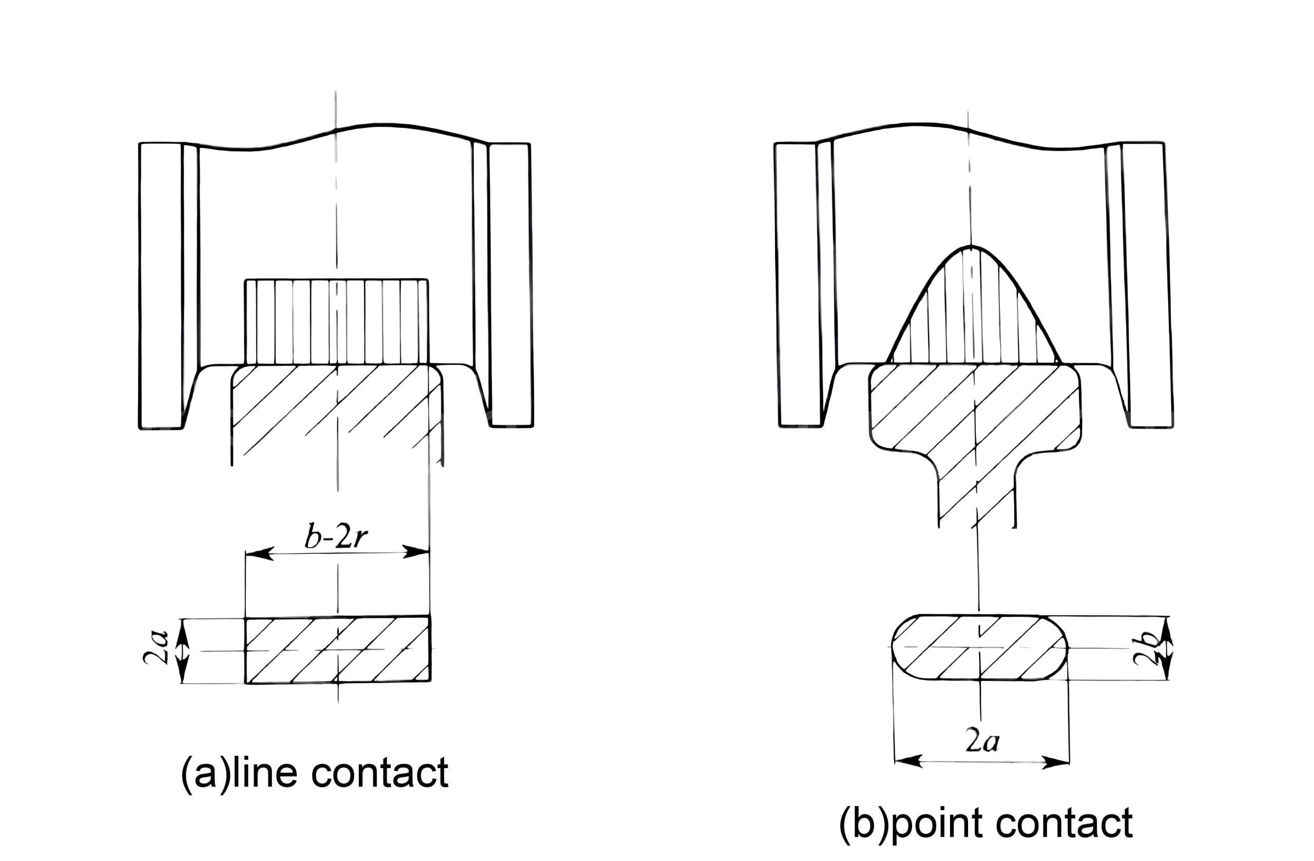
2. Wheel Tread Contact Strength Calculation:
2.1 Allowable Wheel Pressure for Line Contact:
Pc≤K1×D×L×C1×C2
PC —- wheel fatigue calculation load (N);
K1 —– permissible line contact stress constant (N/mm2) related to the material, selected according to Table 1;
D —– wheel diameter (mm);
L—— effective contact length of the wheel and the track;
C1—– speed coefficient, selected according to Table 2;
C2—– working level coefficient, selected according to Table 3;
Schedule of calculation factors (Table 1):
σb
K1
K2
500
3.8
0.053
600
5.6
0.1
650
6.0
0.132
700
6.8
0.181
800
7.2
0.245
Schedule of Coefficients for Calculating Wheel Tread Contact Strength 1
Notes:
1. σb is the tensile strength of the material (N/mm2);
2. Steel wheels should generally be heat-treated, tread hardness is recommended to be HB=300~380, and the depth of quenching layer is 15mm~20mm. In determining the permitted value, σb is taken when the material is not heat-treated;
3. When the wheel material adopts ductile iron; σb.≥500N/mm2 material, K1, K2 value is selected according to σb.=500N/mm2.
Schedule of calculation factors (Table 2):
RPM
C1
RPM
C1
RPM
C1
min-1
min-1
min-1
200
0.66
50
0.94
16
1.09
160
0.72
45
0.96
14
1.1
125
0.77
40
0.97
12.5
1.11
112
0.79
35.5
0.99
11.2
1.12
100
0.82
31.5
1.00
10
1.13
90
0.84
28
1.02
8
1.14
80
0.87
25
1.03
6.3
1.15
71
0.89
22.4
1.04
5.6
1.16
63
0.91
20
1.06
5
1.17
56
0.92
18
1.07
Schedule of Coefficients for Calculating Wheel Tread Contact Strength 2
Schedule of calculation factors (Table 3):
Operating Organization Working Level
C2
M1~M3
1.25
M4
1.12
M5
1.00
M6
0.9
M7、M8
0.8
Schedule of Coefficients for Calculating Wheel Tread Contact Strength 3
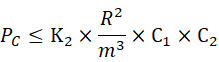
2.2 Allowable Wheel Pressure for Point Contact:
PC —- wheel fatigue calculation load (N);
K2 —– material-related permissible point contact stress constant (N/mm2), selected according to Table 1;
R —– radius of curvature, take the radius of curvature of the wheel and the radius of curvature of the track of the greater value (mm);
M —— by the top surface of the track and the wheel’s radius of curvature of the ratio (r/R), according to the Table 4 selected;
C1 —– Speed coefficient, selected according to Table 3;
C2 —– working level coefficient, selected according to Table 4;
Schedule of calculation factors (Table 4):
r/R
1.0
0.9
0.8
0.7
0.6
0.5
0.4
0.3
m
0.388
0.400
0.420
0.440
0.468
0.490
0.536
0.600
Schedule of Coefficients for Calculating Wheel Tread Contact Strength 4
Notes:
1. m values are calculated by interpolation when r/R is some other value;
2. r is the small value of the radius of curvature of the contact surface
The above calculations can be used to verify the verification of wheels with set diameters, in order to determine the effective maximum load carrying capacity of the wheels and the reasonableness of the dimensions (diameter of the wheels, dimensions of the wheels and the track fit, etc.).
Maximum permissible wheel pressure table for wheel sets of large vehicles:
Wheel Diameter/mm
Rail Model
Working Level
Running Speed/(m/min)
Q/C
<60
60~90
>90~180
1.1
0.5
0.15
1.1
0.5
0.15
1.1
0.5
0.15
500
P38
M1~M3
20.6
19.7
18
18.7
17.9
16.4
17.2
16.4
15
M4、M5
17.2
16.4
15
15.6
15
13.7
14.4
13.7
12.5
M6、M7
14.7
14.1
12.9
13.4
12.8
11.7
12.3
11.7
10.7
M8
12.9
12.3
11.3
11.7
11.2
10.3
10.7
10.3
9.4
QU70
M1~M3
26
24.3
22.7
23.6
22.6
20.6
21.7
20.7
19
M4、M5
21.7
20.7
19
19.7
18.9
17.2
18.1
17.3
15.9
M6、M7
18.6
17.7
16.2
16.9
16.2
14.7
15.5
14.8
13.6
M8
16.3
15.5
14.2
14.8
14.1
12.9
13.6
12.9
11.6
600
P38P43
M1~M3
24.6
23.5
21.5
22.4
21.4
19.5
20.6
19.6
18
M4、M5
20.6
19.6
18
19.7
17.8
16.3
17.2
16.4
15
M6、M7
17.6
16.8
15.4
16
15.3
14
14.7
14
12.9
M8
15.4
14.7
13.4
14
13.4
12.2
12.9
12.3
11.3
QU70
M1~M3
32
30.5
27.9
29.2
27.8
25.4
26.7
25.5
23.3
M4、M5
26.7
25.5
23.3
24.4
23.2
21.2
22.3
21.3
19.4
M6、M7
22.9
21.8
19.9
20.9
19.9
18.1
19.1
18.2
16.7
M8
20
19.1
17.4
18.3
17.4
15.8
16.7
15.9
14.0
700
P43
M1~M3
28
26.8
24.5
25.5
24.4
22.3
23.4
22.4
20.4
M4、M5
23.4
22.4
20.4
21.3
20.4
18.6
19.5
18.7
17
M6、M7
20
19.2
17.5
18.3
17.4
15.9
16.7
16
14.6
M8
17.5
16.7
15.3
15.9
15.2
13.9
14.6
14
12.7
QU70
M1~M3
38.6
36.8
33.6
35.2
33.5
30.6
32.2
30.7
28
M4、M5
32.2
30.726
28
29.4
28
25.6
26.9
25.6
23.4
M6、M7
27.6
3
24
25.2
24
21.9
23
22
20
M8
24.2
23
21
22
21
19.1
20.1
19.2
17.5
800
QU70
M1~M3
43.7
41.7
38.1
39.8
38
34.7
36.4
34.8
31.8
M4、M5
36.4
34.8
31.8
33.2
31.7
29
30.4
29
26.6
M6、M7
31.2
29.8
27.2
28.4
27.2
24.8
26
24.9
22.7
M8
27.3
26.1
23.8
24.9
23.8
21.7
22.8
21.8
19.8
900
QU80
M1~M3
50.5
48.1
44
46
43.7
40
42.2
40.2
36.8
M4、M5
42.4
40.2
36.8
38.4
36.5
33.4
35.2
33.6
30.7
M6、M7
36.1
34.4
31.5
32.9
31.2
28.6
30.2
28.8
26.3
M8
31.6
30.1
27.5
28.8
27.3
25
26.4
25.1
23
Maximum Permissible Wheel Pressure Table for Wheel Sets of Large Vehicles
Maximum permissible wheel pressure table for trolley wheel sets:
Wheel Diameter/mm
Rail Model
Working Level
Running Speed/(m/min)
Q/C
<60
60~90
>90~180
>180
≥1.6
0.9
≥1.6
0.9
≥1.6
0.9
≥1.6
0.9
250
P11
M1~M3
3.3
3.09
2.91
2.81
2.67
2.58
2.46
2.34
M4、M5
2.67
2.58
2.43
2.34
2.23
2.15
2.5
1.98
M6、M7
2.38
2.51
2.08
2.01
1.91
1.84
1.76
1.7
M8
2
1.93
1.82
1.76
1.67
1.61
1.54
1.48
350
P18
M1~M3
4.18
4.03
3.8
3.66
3.49
3.36
3.22
3.1
M4、M5
3.49
3.36
3.17
3.06
2.91
2.8
2.68
2.59
M6、M7
2.99
2.88
2.72
2.62
2.5
2.4
3.2
2.22
M8
2.61
2.52
2.38
2.29
2.18
2.1
2.01
1.94
P24
M1~M3
14.1
13.5
12.8
12.3
11.8
11.3
10.9
10.4
M4、M5
11.8
11.3
10.7
10.3
9.85
9.45
9.1
8.7
M6、M7
10.1
9.65
9.15
8.8
8.45
8.1
7.8
7.45
M8
8.8
8.45
8
7.7
7.4
7.06
6.8
6.5
400
P38
M1~M3
16
15.4
14.6
14
13.4
12.8
12.3
11.85
M4、M5
13.4
15.8
12.2
11.7
11.2
10.7
10.3
9.9
M6、M7
11.4
11
10.4
10
9.6
9.15
8.8
8.5
M8
10
9.6
9.15
8.75
8.4
8
7.7
7.4
500
P43
M1~M3
19.8
19.1
18
17.4
16.5
15.9
15.2
14.7
M4、M5
16.5
15.9
15
14.5
13.8
13.3
12.7
12.25
M6、M7
14.15
13.7
12.9
12.45
11.8
11.4
10.9
10.5
M8
12.4
11.9
11.25
10.9
10.3
9.95
9.5
9.2
Maximum Permissible Wheel Pressure Table for Trolley Wheel Sets
Note: This table value is calculated according to the wheel material: ZG310-570, HB320; if the wheel material with ZG50MnMo, wheel axle with 45, HB = 228 ~ 255, the maximum permissible wheel pressure can be increased by 20%;
Q – crane lifting capacity;
G — crane deadweight.
Crane wheel load calculation is the basic work to ensure crane safety, stability and durability. By accurately calculating the wheel load, the design of the crane can be optimized, and the appropriate materials and manufacturing process can be selected, thus improving the overall performance of the equipment. Taken together, crane wheel load calculation is a complex but vital project that must be realized through rigorous analysis and calculation.
Hidden dangers of crane wheels not meeting the standard
Crane wheels not meeting the standard will cause serious impact on the performance, safety and long-term use of the equipment, which is manifested in the following aspects:
1. Increased safety hazards
Wheel breakage or failure: If the wheel material does not meet the standard, it may not be able to withstand the normal load of the crane, and is prone to breakage or serious wear. This will directly threaten the safety of the operator, especially in the case of high load or rapid operation, which may lead to accidents.
Track deflection or derailment: substandard wheels may lead to poor contact between the wheels and the track, causing the crane to deflect or derail, increasing the risk of accidents.
2. Increased wear and damage
Uneven wear: If the quality of the wheels does not meet the standard, there may be defects on their surfaces, such as uneven hardness or uneven structure, leading to uneven wear. This uneven wear accelerates wheel and track damage and increases maintenance costs.
Excessive wear: substandard wheels may wear out too fast during long-term use, leading to changes in wheel dimensions and affecting the stability and operating accuracy of the crane.
3. Affecting operating performance
Imbalance and vibration: substandard quality wheels may cause the crane to run unevenly, generating excessive vibration and noise, affecting operational efficiency and comfort. Long-term vibration may also cause damage to other mechanical components (e.g. bearings, motors, etc.).
Uneven Load Distribution: Quality issues with the wheels may lead to uneven load distribution, especially on cranes with multiple wheel configurations. This will affect the load capacity and working efficiency of the equipment, resulting in the crane not being able to operate efficiently and stably.
4. Reduced equipment life
Early aging and failure: Substandard wheel materials and structures may cause them to be more susceptible to fatigue, corrosion and other damage, thus shortening the overall service life of the crane. The frequency of wheel replacement will increase accordingly, resulting in additional maintenance costs.
Accelerating the wear of other components: substandard wheels may lead to premature wear of other critical crane components (e.g., drive system, rail system, hooks, etc.), which will increase the difficulty and cost of maintenance.
5. Increase maintenance and operation costs
Frequent repairs: substandard wheels will lead to equipment requiring more frequent repairs, replacement or calibration, which not only increases operating costs, but may also lead to increased equipment downtime, affecting productivity.
Early replacement: Low quality wheels may not be able to cope with long term high load demands, resulting in the need for early replacement, increasing maintenance and parts replacement costs.
6. Impact on overall system stability
Damage to the transmission system: Quality problems of the wheels may lead to abnormal operation of the transmission system, such as premature wear or damage to the motor, reducer and other components, thus affecting the stability and operability of the whole crane system.
Track system damage: the impact of substandard wheels on the track system may lead to damage or deformation of the track, which in turn affects the stability of the equipment and may require more frequent track repair and replacement.
Preventive measures:
Strict quality control: Ensure that wheel materials and production processes comply with industry standards, select reliable quality suppliers, and conduct detailed inspections and tests.
Regular inspection and maintenance: Regularly inspect the crane wheels to detect potential wear and cracks in time for necessary maintenance and replacement.
Reasonable design and selection: Select wheels with appropriate specifications according to the working conditions of the crane to ensure that they can withstand the expected load and working environment.
krystal
Crane OEM expert
With 8 years of experience in customizing lifting equipment, helped 10,000+ customers with their pre-sales questions and concerns, if you have any related needs, please feel free to contact me!


.png?w=200&h=134)