Crane Accidental Loads: 5 Design Cases in GB/T 3811-2008

Date: 29 Jul, 2026

Crane accidental loads are loads that do not occur frequently during normal crane operation but may arise occasionally. They include loads caused by in-service wind, snow, ice, temperature changes, and crane skewing. These loads are generally not considered in fatigue failure calculations.

This article summarizes five types of crane accidental loads and their calculation methods: horizontal lateral load Ps during skewing, gradient load, wind load, snow and ice load, and load caused by temperature changes.

1. Crane Accidental Load from Skewing: Ps

The horizontal lateral load generated during crane skewing is an occasional load caused by the reaction of a guiding device, such as a guide roller or wheel flange, when a wheeled crane or trolley travels longitudinally or transversely in a steady state.

2Horizontal lateral load calculation for crane skewing
Horizontal lateral load calculation for crane skewing

Where:

  • ∑P — Sum of the maximum wheel loads: the sum of the frequently occurring maximum wheel loads on the wheels associated with the effective wheelbase on the end carriage at the side subjected to the lateral load.
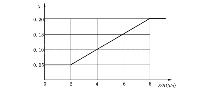
  • λ — Horizontal lateral load coefficient. It depends on the ratio S/B (or S/a), where S is the crane span, B is the crane wheelbase, and a is the effective wheelbase. Determine λ from the figure below.
3Horizontal lateral load coefficient
Horizontal lateral load coefficient λ (Source: GB/T 3811-2008, Figure D.2)

For a multi-wheel crane, using the effective wheelbase a instead of the crane wheelbase B provides a more reasonable basis for calculating horizontal lateral force. The principles for determining the effective wheelbase are given in Clause D.2 of GB/T 3811-2008, pages 134–135.

Ps provides a theoretical basis for checking the design of the horizontal wheel assembly. For related operating symptoms and causes, see this guide to overhead crane wheel gnawing and rail skewing.

2. Crane Gradient Load

A crane gradient load is the component, acting along the inclined surface of a slope, road, or rail, of the crane self-weight and rated lifting load.

  1. Mobile cranes: Where calculation is required, consider the actual road or ground conditions.
  2. Rail-mounted cranes, including railway cranes: Where the track gradient does not exceed 0.5% (0.29°), the gradient load is not considered. Otherwise, calculate the gradient load using the actual gradient.
  3. According to the crane rail top straightness tolerances in Table 2 of GB/T 10183.1-2018, Cranes—Wheels and Travel and Traversing Tracks Tolerances—Part 1: General, the gradient of a rail-mounted overhead or gantry crane track should not exceed 1/1000 for tolerance class 2, or 0.5/1000 for tolerance class 1 when the overhead crane travel speed is ≥112 m/min. The trolley track gradient should not exceed 0.5/1000 for tolerance class 2 or 1. This is an equivalent inference and the original author's personal opinion; no explicit general gradient requirement had been found.
  4. Shipbuilding gantry crane: Welded rails should be used, and the travel track gradient should not exceed 1/1000 (GB/T 27997-2026).
  5. Reach stacker: The ground gradient should not exceed 3% (GB/T 26474-2026).
  6. Rubber-tyred container gantry crane: The ground gradient of the travel path should not exceed 1%, and the local gradient should not exceed 3% (GB/T 14783-2009).

Based on these requirements, if the on-site track installation complies with the applicable standard, is it unnecessary to calculate the gradient load for a rail-mounted crane? If the gradient load must be calculated, does this indicate that the specified installation condition does not comply with the standard? These are questions raised in the original article.

3. Crane Wind Load PW

Wind load shall be considered for cranes operating outdoors. Wind load is assumed to be a static load acting in the most unfavorable horizontal direction. Select the calculated wind pressure according to the crane type and operating region.

3.1 Calculated Wind Pressure

4Calculated wind pressure formula
Calculated wind pressure formula

Where:

  • p — Calculated wind pressure, in newtons per square metre (N/m²).
  • Vs — Calculated wind speed, in metres per second (m/s).

The calculated wind speed is the gust wind speed at a height of 10 m above open terrain, expressed as the average instantaneous wind speed over a 3 s interval.

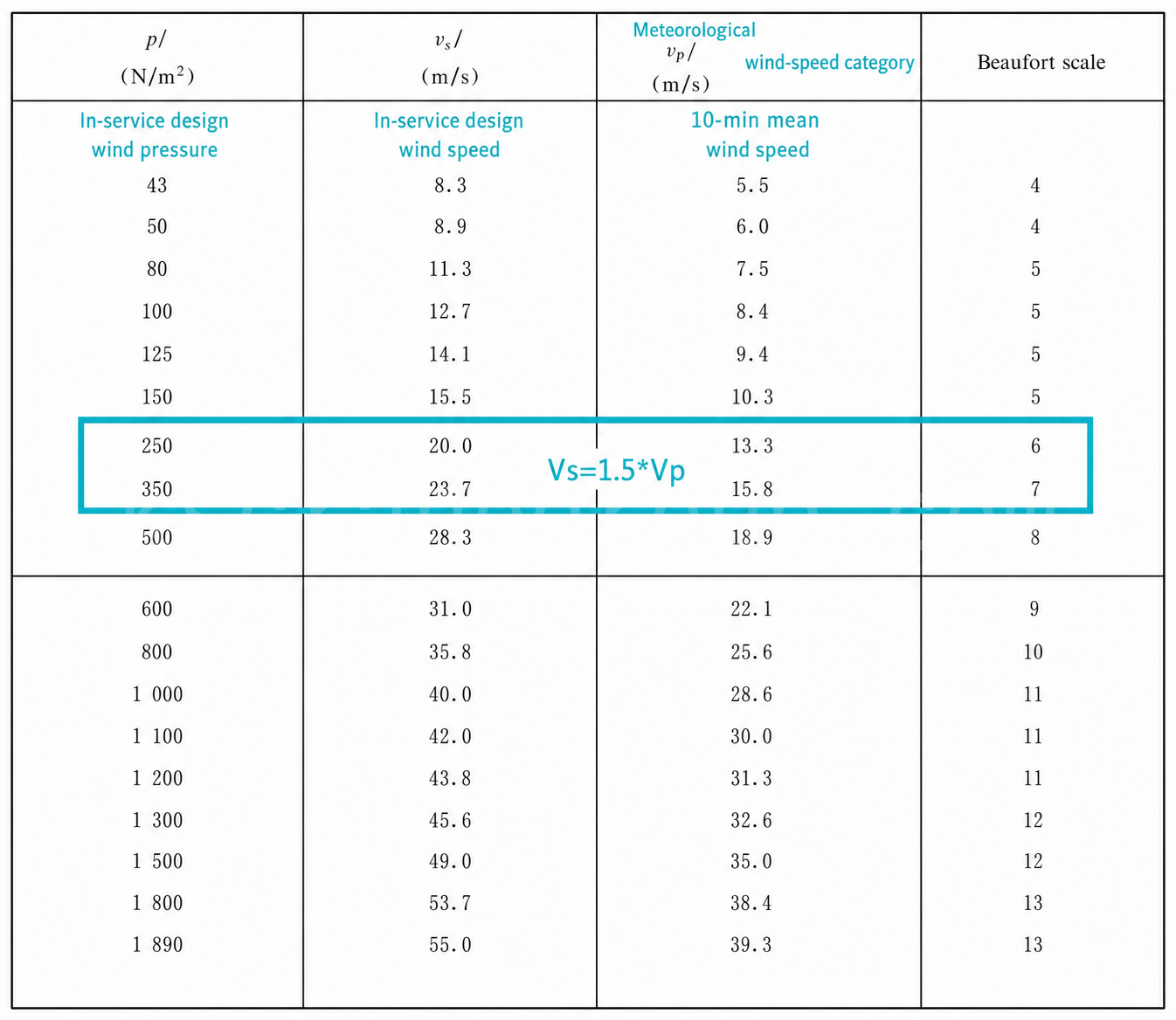
For the in-service condition, the gust wind speed is 1.5 times the mean wind speed over a 10 min interval.

For the out-of-service condition, the gust wind speed is 1.4 times the mean wind speed over a 10 min interval.

5Table 1 Relationship among calculated wind pressure p 3 s mean instantaneous wind speed Vs 10 min mean wind speed Vp and Beaufort force
Table 1 Relationship among calculated wind pressure p, 3 s mean instantaneous wind speed Vs, 10 min mean wind speed Vp, and Beaufort force (Source: GB/T 3811-2008, Table E.1, page 137)

3.2 In-Service Wind Load PWⅡ

The in-service wind load is the maximum wind force that a crane shall be capable of withstanding while operating.

The in-service wind pressure is taken as constant over the full crane height, without considering variation with height.

Where a wind speed measuring device is used to prevent operation above the limiting wind speed, it is normally installed at the highest point of the crane.

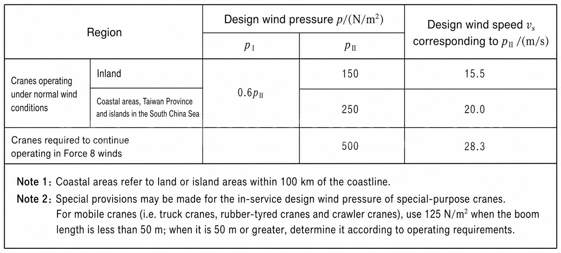
The calculated in-service wind pressure is divided into PⅠ and PⅡ. The corresponding wind pressures and wind speeds are shown below. If a manufacturer uses wind speeds or wind pressures different from the tabulated values, these values shall be stated in the crane design documentation and operating instructions. In practice, the project technical specification normally governs.

Table 2 Calculated in-service wind pressure and wind speed (Source: GB/T 3811-2008, Table 15)
  • PⅠ is the normal calculated wind pressure for the in-service condition. It is used to calculate resistance for motor power selection and for thermal verification.
  • PⅡ is the maximum calculated wind pressure for the in-service condition. It is used to calculate the strength of mechanism components and metal structures, structural rigidity and stability, drive overload capacity, overall crane stability against overturning, and wind-resistant anti-slip safety.

3.3 In-Service Wind Load Acting on the Crane

7Formula for in service wind load acting on a crane
Formula for in-service wind load acting on a crane

Where:

  • PWⅠ — Normal in-service wind load acting on the crane, in newtons (N).
  • PWⅡ — Maximum in-service wind load acting on the crane, in newtons (N).
  • C — Wind force coefficient.
  • PⅠ and PⅡ — The two calculated in-service wind pressures, in N/m².
  • A — Solid windward area of the crane component perpendicular to the wind direction, in square metres (m²). It is equal to the outline windward area A0 multiplied by the solidity ratio Φ of the windward face: A=A0Φ.
  • θ — Angle between the wind direction and the longitudinal axis of the component or the surface of the structure (θ≤90°), in degrees.

The total wind load on the crane structure is the sum of the wind loads acting on its individual parts.

  1. For the wind force coefficient C, refer to Clause 4.2.2.3 of GB/T 3811-2008. It includes wind force coefficients for individual members, single-plane truss structures, and square lattice towers.
  2. The windward area A is related to the shielding reduction factor. For example, for calculation of the windward area of the main girders of a double-girder gantry crane, refer to Clause 4.2.2.3.6 of GB/T 3811-2008. It covers shielding reduction for two members, shielding reduction for the members listed in the original standard, spacing ratios, and other factors.

For practical equipment selection after the design load has been established, see the KSCRANE Gantry Crane Wind Protection System Selection Guide.

3.4 Wind Load Acting on the Lifted Load

8Formula for in service wind load acting on a lifted load
Formula for in-service wind load acting on a lifted load

Where:

  • PWQⅠ — Normal in-service wind load acting on the lifted load, in newtons (N).
  • PWQⅡ — Maximum in-service wind load acting on the lifted load, in newtons (N).
  • AQ — Maximum windward area of the lifted load, in square metres (m²).

Where a crane handles loads of specific dimensions and shapes, determine the windward area from the corresponding dimensions and profile. Where the area is not known, estimate the windward area in accordance with Clause E.5 of Annex E in GB/T 3811-2008.

4. Snow and Ice Loads

Snow and ice loads shall be considered in certain regions. The increase in windward area caused by accumulated ice and snow shall also be considered.

5. Loads Caused by Temperature Changes

This section is theoretical and is provided for reference. Temperature load is generally not considered. However, it shall be considered in certain regions where the temperature during crane installation differs greatly from the temperature during use, or for large-span statically indeterminate structures. One example is a gantry crane with two rigid legs and a span of 30 m or more. In such cases, constrained expansion or contraction of structural members caused by temperature changes generates a load. The calculation may be based on relevant information provided by the user.

6. GB/T 45680-2025 for Crane Wind Load Assessment

GB/T 45680-2025, Cranes—Wind Load Assessment(query of Chinese crane standards), is a newly developed first-edition standard for crane wind load calculation. It is a modified adoption (MOD) of ISO 4302:2016. It was issued on May 30, 2025, took effect on December 1, 2025, and applies to the calculation of wind loads on cranes in both in-service and out-of-service conditions.

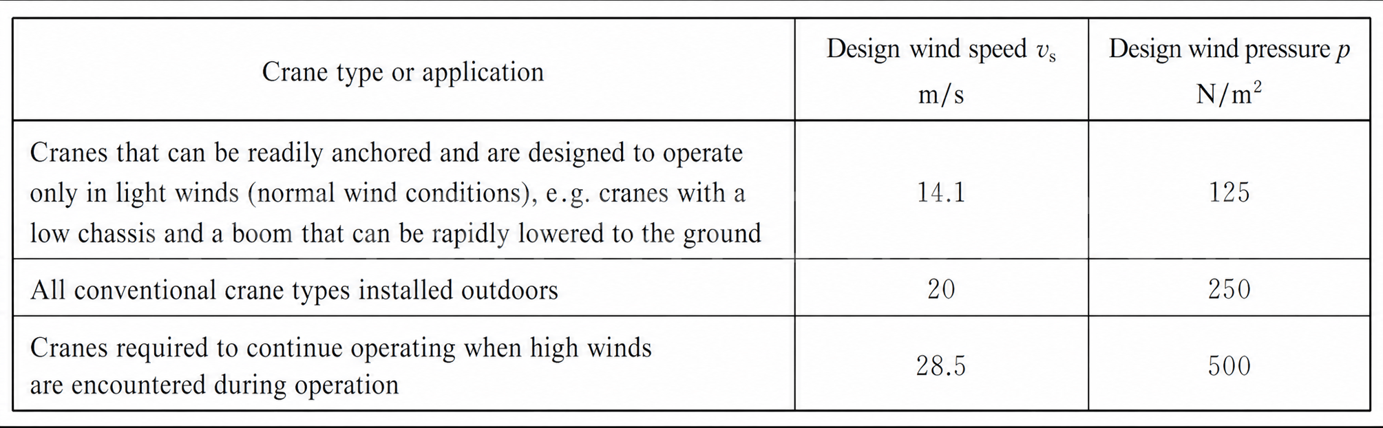
Table 3 In-service design wind speed vs and design wind pressure p (Source: GB/T 45680-2025, Table 2)

The in-service wind speed shall be the wind speed measured at the highest point of the crane.

For an overview of the available hardware used after wind-load assessment, see Gantry Crane Windproof Device Accessories.

Krystal
krystal
Crane OEM expert

With 8 years of experience in customizing lifting equipment, helped 10,000+ customers with their pre-sales questions and concerns, if you have any related needs, please feel free to contact me!

TAGS: Crane Accidental Loads,Crane Design,Crane Load Calculation,Crane Skewing,gantry crane,GB/T 3811,overhead crane,Snow and Ice Load,Temperature Load,Wind Load
English
Español Português do Brasil Русский Français Deutsch 日本語 한국어 العربية Italiano Nederlands Svenska Polski ไทย Türkçe हिन्दी Bahasa Indonesia Bahasa Melayu Tiếng Việt 简体中文 বাংলা فارسی Pilipino اردو Українська Čeština Беларуская мова Kiswahili Dansk Norsk Ελληνικά English