Overhead Crane Wind Load Calculation: Complete Guide to Wind Speed, Wind Pressure and Design Limits

Date: 15 Jul, 2026

Overhead crane wind load calculation is one of the most important aspects of crane structural design and safe outdoor operation. Whether designing an overhead cranes, gantry cranes, RTG, RMG, or ship-to-shore container crane, engineers must accurately determine design wind speed, wind pressure, and operating wind limits to ensure structural strength, stability, and anti-overturning performance. Incorrect wind load calculations can result in excessive structural stress, crane derailment, sliding, overturning, or severe equipment damage during strong winds or typhoon conditions.

Overhead Crane Wind Load Calculation Complete Guide to Wind Speed Wind Pressure and Design Limits

This guide explains the engineering principles behind crane wind load calculation based on GB/T 3811-2008, GB/T 6067.1-2010, GB/T 28591-2012, and GB/T 43237-2023, covering wind pressure formulas, wind speed conversions, Beaufort wind force classifications, typhoon categories, and the operating wind speed limits for different types of cranes.

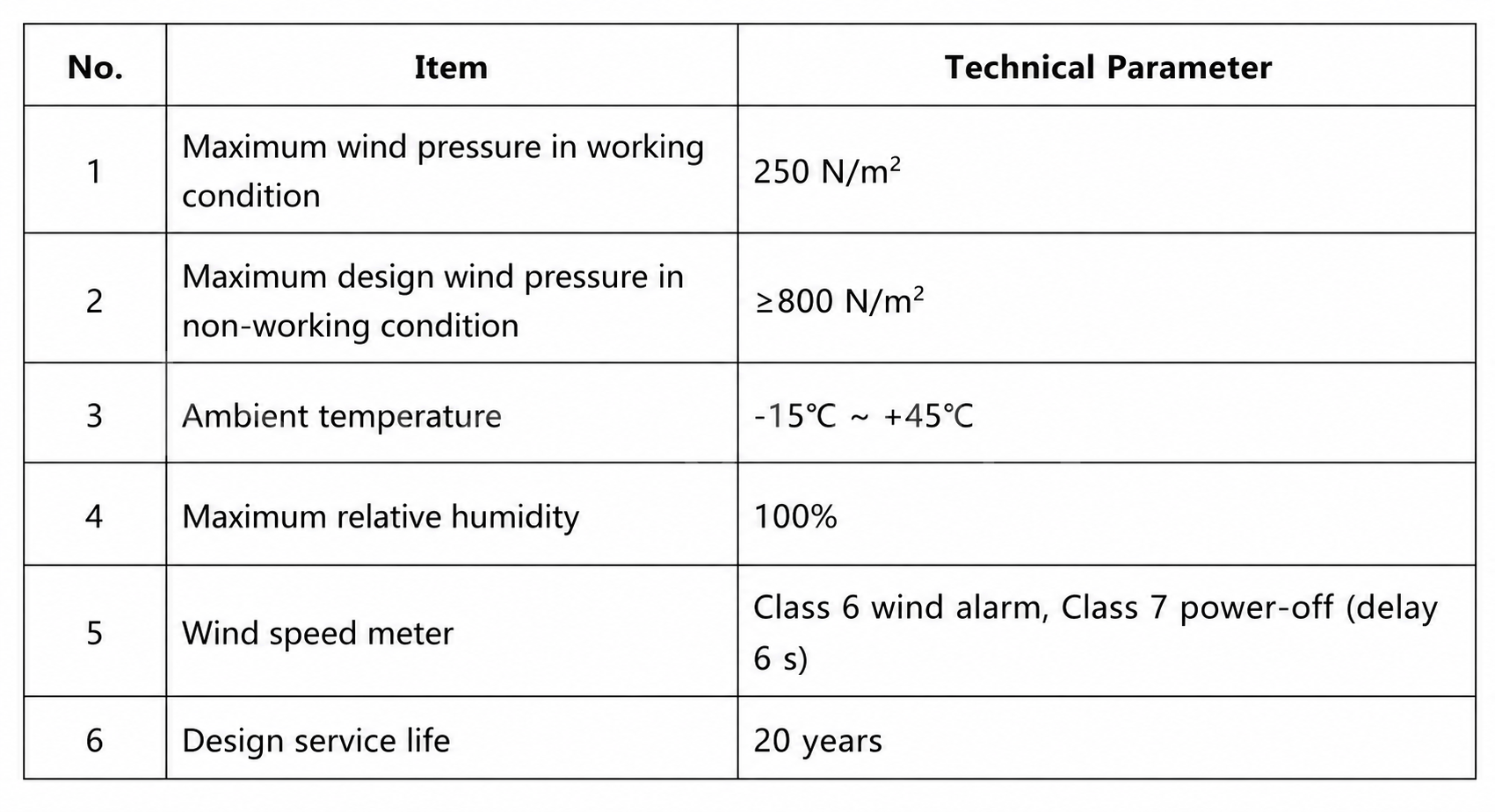
Table 1 Wind speed design parameters for a project crane specification

1. Anemometer and Wind Speed Alarm Requirements

  1. For outdoor high-rise cranes, an anemometer shall be installed at an elevated windward position on the crane. (GB/T 6067.1, Clause 9.6.1.1)

  2. Outdoor high-rise cranes shall be equipped with a wind speed alarm device that displays instantaneous wind speed, and shall emit an alarm signal when the wind force exceeds the in-service design wind speed threshold. (Clause 9.6.1.2)
  3. Crane operation is prohibited when the wind speed exceeds the manufacturer’s specified maximum working wind speed. (Clause 17.1)

2. Design Wind Speed and Design Wind Pressure

In-service design wind pressure is divided into two levels:

  • pⅠ — normal working condition design wind pressure, used for motor power selection (resistance calculation and thermal verification)
  • pⅡ — maximum in-service design wind pressure, used for strength, rigidity and stability checks of structural components, verification of drive overload capacity, and in-service anti-overturning stability and anti-skid safety

pⅠ = 0.6 × pⅡ

Out-of-service design wind pressure pⅢ is the maximum wind pressure the crane must withstand when not in operation. It is used for out-of-service strength checks, anti-overturning stability verification, and the design of rail clamps, anchor devices, and storm ties.

The fundamental wind pressure–wind speed relationship (applicable to both in-service and out-of-service conditions):

p = 0.625 × Vs²

SymbolMeaningUnit
pDesign wind pressureN/m²
VsDesign wind speed (3-second gust)m/s
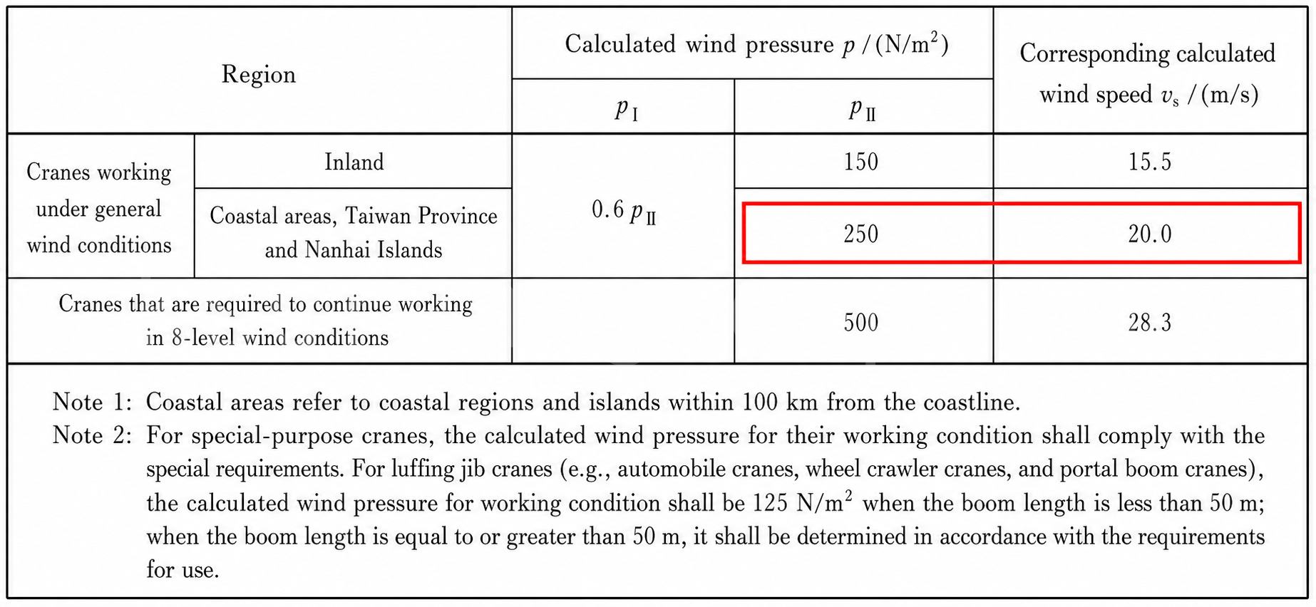
Table 2 In-service design wind pressure and design wind speed (Source: GB/T 3811-2008 Table 15)

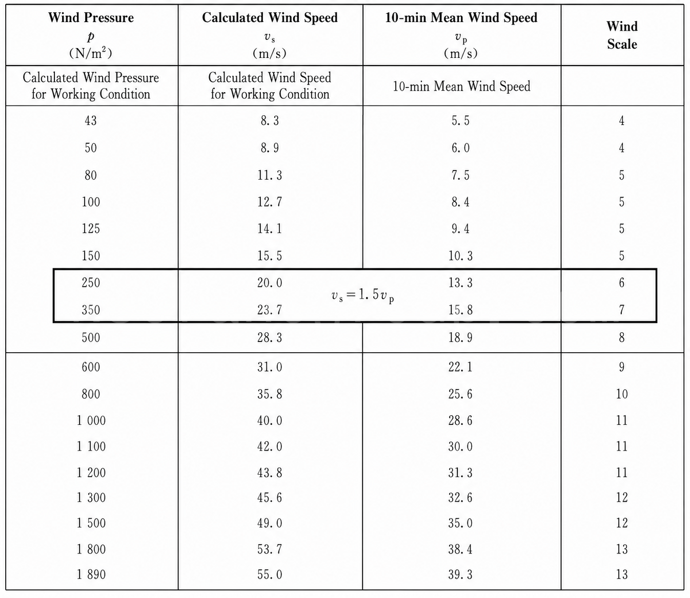
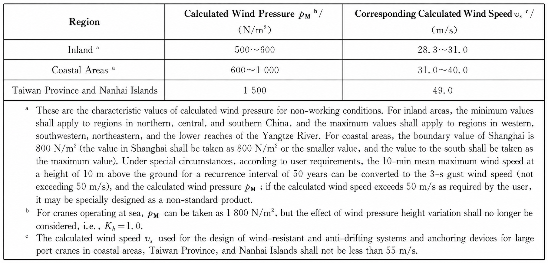
Key conversion relationship: The design wind speed Vs is a 3-second gust measured at 10 m height in open terrain. For in-service conditions, Vs = 10-minute mean wind speed × 1.5 (see Table 3). For out-of-service conditions, Vs = 10-minute mean wind speed × 1.4 (see Table 4). The 10-minute mean wind speed is the meteorological wind force scale reference.

3Table 3 Relationship between design wind pressure p 3 s gust speed Vs 10 min mean wind speed Vp and wind force scale
Table 3 Relationship between design wind pressure p, 3 s gust speed Vs, 10 min mean wind speed Vp, and wind force scale (Source: GB/T 3811-2008 Table E.1)
Table 4 Out-of-service design wind pressure and design wind speed (Source: GB/T 3811-2008 Table 18)

The Core Derivation

From Tables 2 and 3, for cranes operating under normal wind conditions:

  • Maximum design wind pressure: 250 N/m²
  • Maximum design wind speed (gust): 20 m/s
  • Corresponding wind force: Force 6

This is why the wind speed alarm must trigger at Force 6 — it is the limiting gust speed for which the crane structure and stability are designed in normal service.

From Table 4, for inland cranes in the out-of-service condition:

  • Minimum out-of-service design wind pressure: 500 N/m²
  • Minimum out-of-service design wind speed (gust): 28.3 m/s
  • Corresponding wind force: Force 8

This is why the crane must be anchored at Force 8 — it is the minimum out-of-service design condition for inland cranes.

3. Wind Force Scale Classification

3.1 Terminology

  • Wind speed: the horizontal distance travelled by air per unit time. Common units: m/s, km/h, or knots. (GB/T 28591-2012)
  • Wind force: the intensity of wind, commonly expressed in wind force scale numbers. The Beaufort scale is used internationally. (GB/T 28591-2012)

3.2 Wind Force Scale

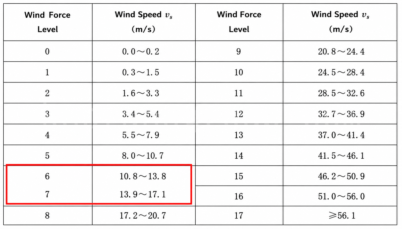
Per GB/T 28591-2012 Wind Force Scale, wind force is classified into 18 levels: 0 through 17.

Table 5 Wind force scale classification (Source: GB/T 28591-2012)

3.3 Beaufort Wind Force Scale

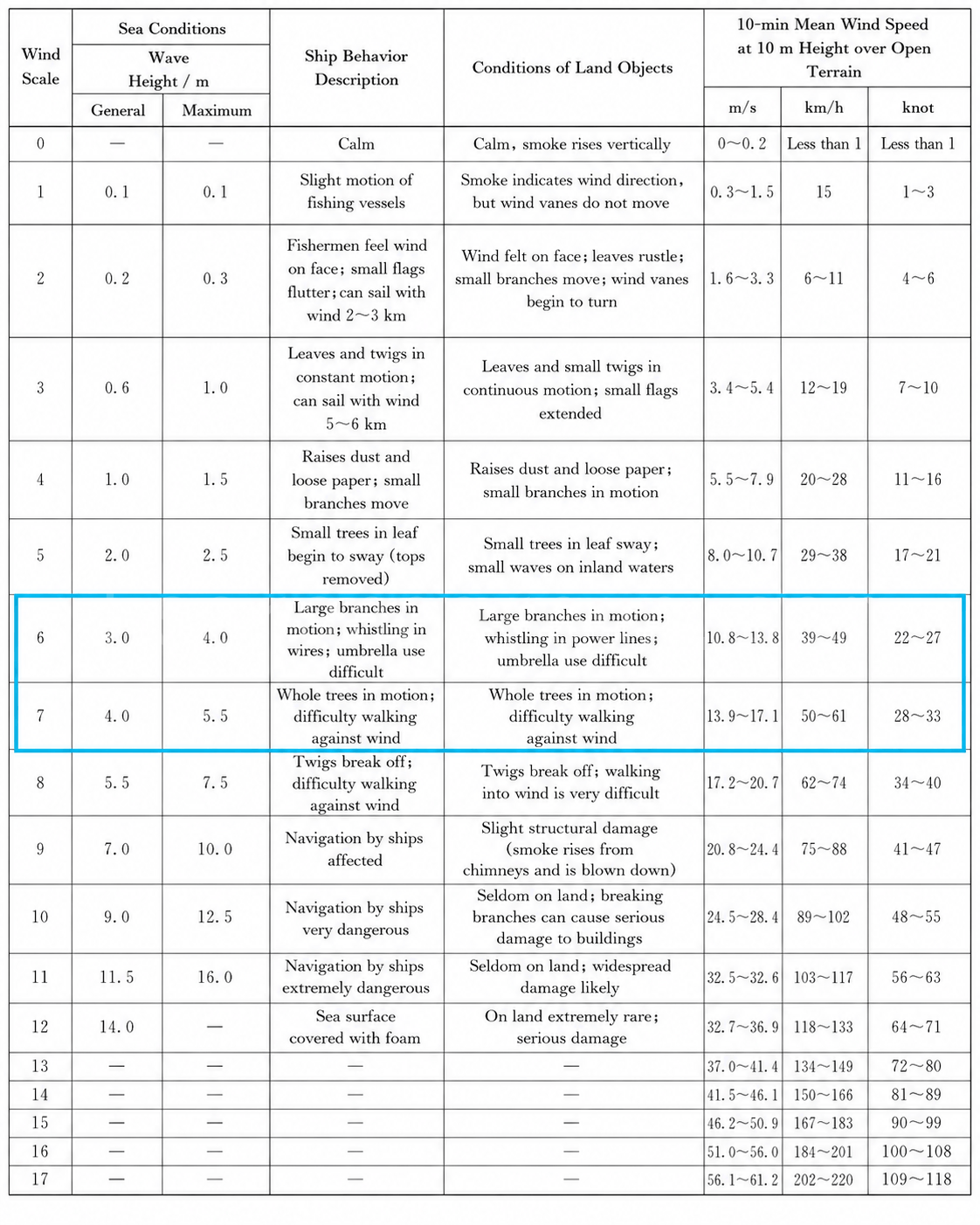
The Beaufort scale was devised by Francis Beaufort (1774–1857) in 1805 and expanded in 1946. It correlates wind force levels with observable land surface features.

6able 6 Beaufort wind force scale with land features
Table 6 Beaufort wind force scale with land features (Source: GB/T 28591-2012)

4. Typhoon Classification

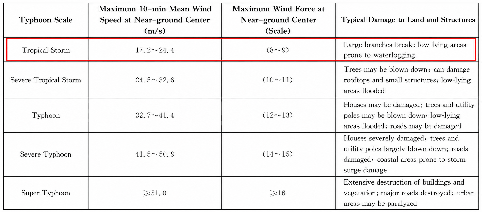
Typhoons are classified into five intensity levels: tropical storm, severe tropical storm, typhoon, severe typhoon, and super typhoon. Maximum mean wind speeds near the centre and corresponding land surface features are detailed in Table 7.

Table 7 Typhoon categories — maximum mean wind speed near centre and land features (Source: GB/T 43237-2023)

5. Crane Operating Wind Speed Limits by Type

#Crane TypeStandardIn-Service LimitOut-of-Service Limit
1General gantry craneGB/T 14406-2011Inland ≤150 Pa (F5), Coastal ≤250 Pa (F6)
2Electric hoist gantry craneJB/T 5663-2008Inland ≤150 Pa (F5), Coastal ≤250 Pa (F6)≤800 Pa (F10)
3RTG container craneGB/T 14783-2009≤20 m/s (F6)≤44 m/s (F11)
4RMG container craneGB/T 19683-2005≤20 m/s (F6)
5Ship-to-shore container craneGB/T 15361-2009≤20 m/s (F6)≤50 m/s (F12)
6Shipbuilding gantry craneGB/T 27997-2011≤250 Pa (F6)≤1,000 Pa (F11); coastal anchoring ≥55 m/s (F13)
7Bridge-type grab ship unloaderGB/T 26475-2021≤20 m/s (F6)≤49 m/s (F12); coastal anchoring ≥55 m/s (F13)
8Portal craneGB/T 29560-2013Per GB/T 3811 Table 15Per GB/T 3811 Table 18
9Bridge girder erection machineGB/T 26470-2011Traversing ≥150 Pa (F5), erecting ≥250 Pa (F6)≥1,200 Pa (F11)
10Tower craneGB/T 5031-2019≤20 m/s (F6); erection ≤12 m/s (F5)See Table 8
11Truck craneJB/T 9738-2015≤14.1 m/s (F5); retract jib at ≥15.5 m/s; retract boom at ≥20 m/s (F6)
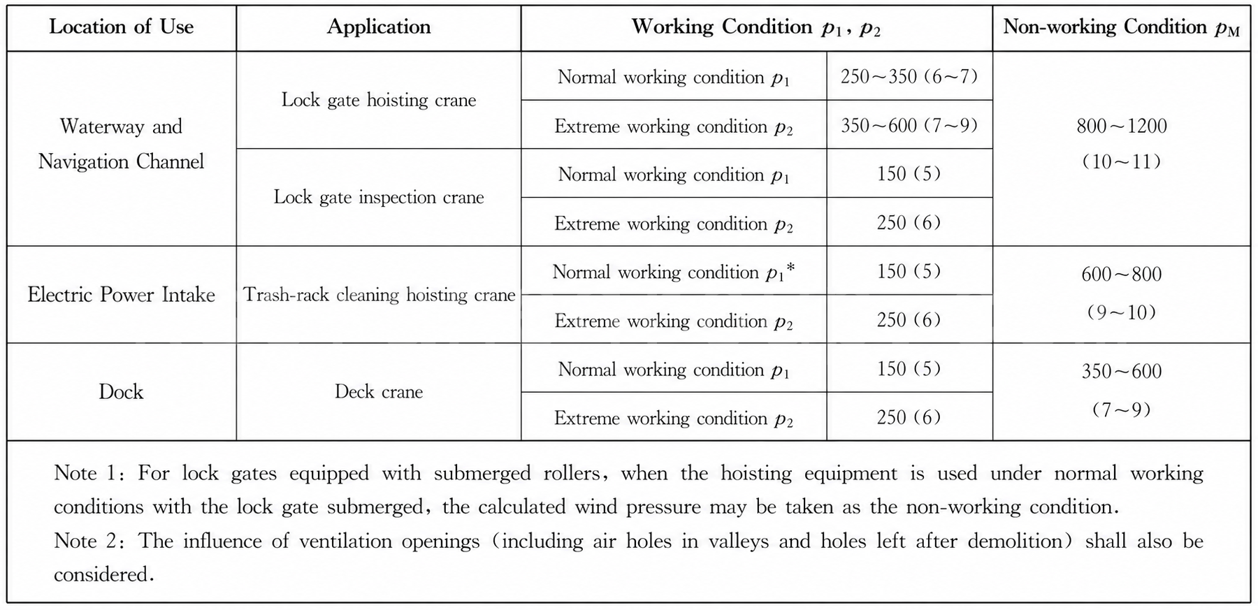
12Hydropower station gantry craneJB/T 6128-2008See Table 9See Table 9
Table 8 Hydropower station gantry crane out-of-service design wind pressure and wind speed (Source: JB/T 6128-2008)

Note: The wind speeds listed in items 1–12 above are all design wind speeds — i.e. 3-second gust speeds, which are 1.5× or 1.4× the meteorological wind force classification reference values. For crane types not listed, refer to the applicable product standard.

6. Overhead Crane Wind Load Calculation Summary

Wind ForceThreshold (10-min mean)3 s Gust VsDesign Wind PressureRequired Action
Force 610.8–13.8 m/s20 m/s250 N/m²Alarm — crane is at its maximum in-service design condition; alert operator to monitor conditions and prepare
Force 713.9–17.1 m/s~22–25 m/sShutdown & lock — wind has exceeded the design working limits of the vast majority of cranes; stop all operation, prevent manual override
Force 817.2–20.7 m/s28.3 m/s≥500 N/m²Anchor — tropical-storm-level winds; engage all rail clamps, anchor devices, and storm tie-downs
Special cases such as wind-resistant port cranes, military cranes, and rescue cranes may have different thresholds. For all standard overhead cranes and gantry cranes, the Force 6/7/8 rule holds.

7.Overhead Crane Wind Load Calculation: Key Engineering Takeaways

Accurate Overhead Crane Wind Load Calculation is fundamental to the safe design, operation, and maintenance of outdoor lifting equipment. By correctly determining design wind speed, wind pressure, load combinations, and operating wind limits, engineers can optimize structural design, improve anti-overturning stability, and select appropriate wind protection devices such as anemometers, rail clamps, anchor systems, and storm tie-downs. Understanding the relationship between meteorological wind data, design wind pressure, and crane operating conditions is equally important for preventing wind-related failures and ensuring safe lifting operations.

Following the calculation methods and design requirements specified in GB/T 3811, together with the safety provisions of GB/T 6067.1 and the applicable crane product standards, enables manufacturers, designers, and maintenance teams to establish reliable wind load assessment procedures for overhead cranes, gantry cranes, RTGs, RMGs, ship-to-shore cranes, and other outdoor lifting equipment. Proper wind load calculation not only improves operational safety but also extends equipment service life and enhances long-term reliability in harsh environmental conditions.

Principal Reference Standards(Query of Chinese Crane Standards):

  • GB/T 6067.1-2010 Safety rules for lifting appliances — Part 1: General
  • GB/T 3811-2008 Design rules for cranes
  • GB/T 43237-2023 Public meteorological disaster prevention guidance — Typhoon
  • GB/T 28591-2012 Wind scale
Krystal
krystal
Crane OEM expert

With 8 years of experience in customizing lifting equipment, helped 10,000+ customers with their pre-sales questions and concerns, if you have any related needs, please feel free to contact me!

TAGS: Anemometer,Crane Design,Crane Safety,gantry crane,GB/T 3811,overhead crane,Typhoon Classification,Wind Force Scale,Wind Protection,Wind Speed Alarm
English
Español Português do Brasil Русский Français Deutsch 日本語 한국어 العربية Italiano Nederlands Svenska Polski ไทย Türkçe हिन्दी Bahasa Indonesia Bahasa Melayu Tiếng Việt 简体中文 বাংলা فارسی Pilipino اردو Українська Čeština Беларуская мова Kiswahili Dansk Norsk Ελληνικά English