Overhead Crane Wire Rope Selection: The Complete Guide to Safe Drum and Sheave Design

Date: 07 Jul, 2026

Wire rope, drums, and sheaves are the core components of any overhead crane or hoist lifting mechanism. When specifying these components, what minimum safety factor should you use? How do you calculate the required minimum breaking force? What diameter should your drum and sheave be?

Overhead Crane Wire Rope Selection explained with GB/T 34529-2017 (ISO 16625). Learn how to calculate minimum breaking force, choose the correct wire rope safety factor, determine drum and sheave diameters, control fleet angles, select groove dimensions, and optimize wire rope performance for overhead crane and hoist applications.

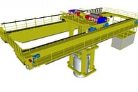
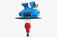
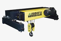
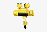
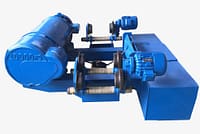
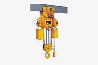
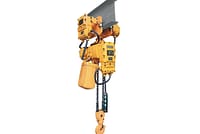
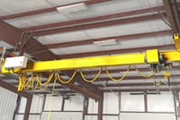
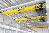
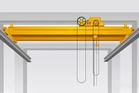
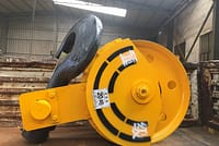
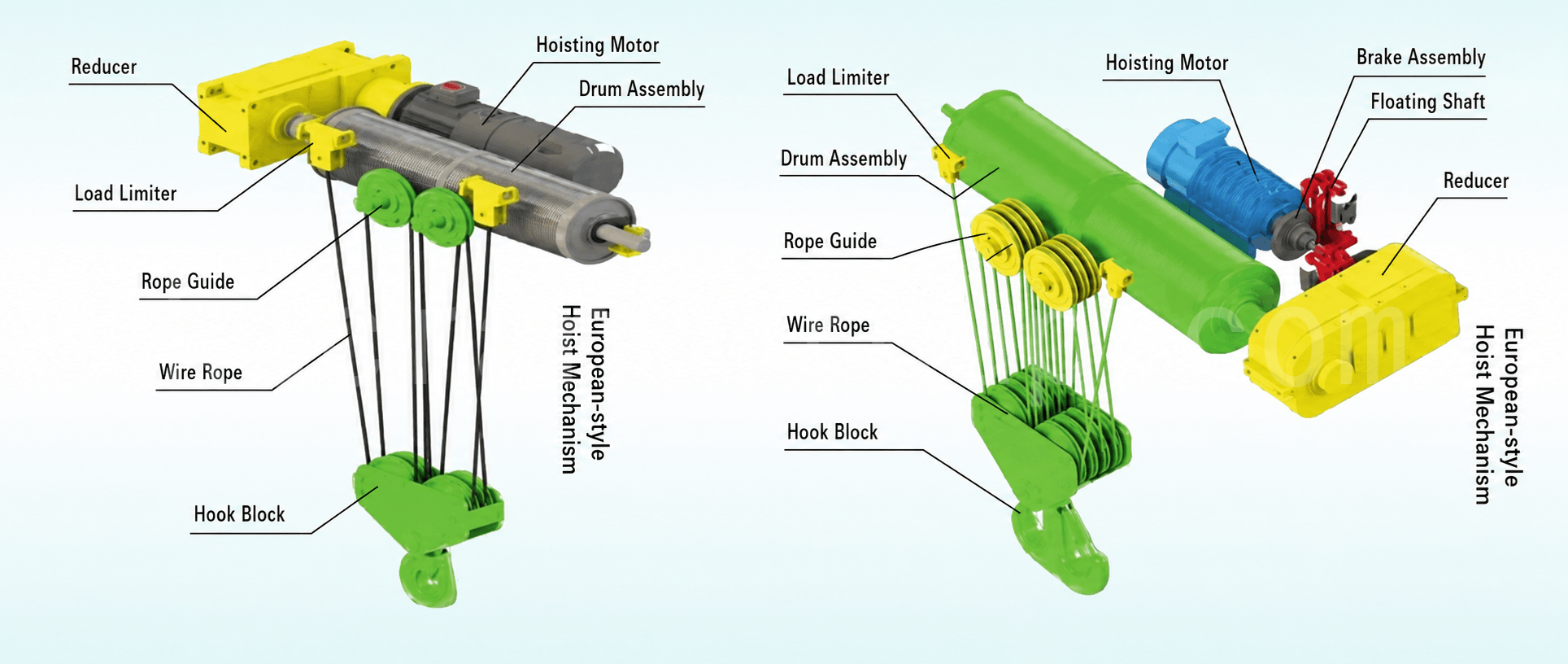
Figure 1 European-style lifting mechanism

1. Scope

This standard applies to the following crane and hoist types (most are defined in ISO 4306-1, corresponding to GB/T 6974.1-2008):

  • Bridge cranes (overhead cranes)
  • Wire rope hoists
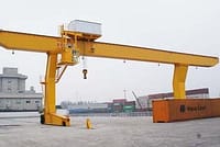
  • Portal or semi-portal cranes
  • Gantry or semi-gantry cranes
  • Cable cranes and portal cable cranes (lifting mechanism and trolley travel mechanism only)
  • Mobile cranes
  • Tower cranes
  • Railway cranes
  • Floating cranes
  • Deck cranes
  • Derrick cranes and cable-type derrick cranes
  • Rigid-braced derrick cranes
  • Jib cranes (pillar, boom, wall, or bicycle type)
  • General offshore cranes

2. Overhead Crane Wire Rope Minimum Safety Factor Zp

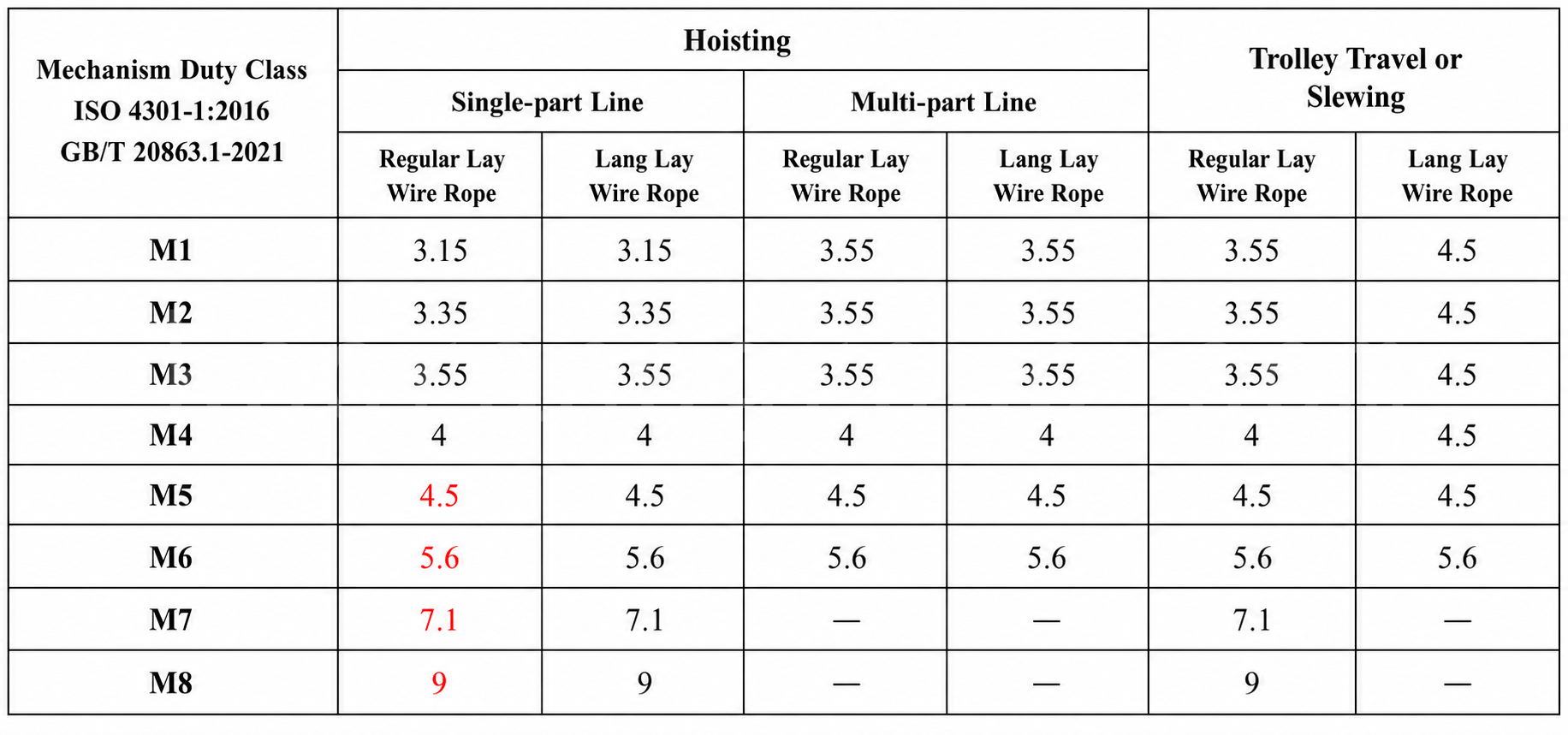
The minimum safety factor for an overhead crane wire rope depends on the mechanism work duty, rope application, reeving arrangement, and rope type.

Table 1 Minimum safety factors for cranes (excluding mobile cranes) and hoists (Source: GB/T 34529-2017)

Items 1–5 are sourced from GB/T 3811-2008 Table 44; items 6–9 are sourced from GB/T 34529-2017 and GB/T 8706-2017.

Key supplementary notes:

  1. For wire ropes handling hazardous loads, select the safety factor from the table at one work-duty level higher than the design classification.
  2. For metallurgical cranes and port container cranes with mechanism work duties M7 or M8, a slightly lower work-duty classification may be used for wire rope selection, provided that rope deterioration can be monitored during service to ensure safe use and timely replacement.
  3. Metallurgical cranes: the minimum safety factor shall not be less than 7.1.
  4. Port container cranes: the minimum safety factor for main hoist ropes and trolley traction ropes shall not be less than 6.
  5. Wire ropes for telescopic booms shall have a safety factor of not less than 4.
  6. Standard wire rope — A collective term for “single-layer strand rope” and “parallel-closed rope”, also referred to as “non-rotation-resistant rope”.
  7. Rotation-resistant wire rope — A multi-strand rope that produces reduced torque or rotation when supporting a load. Rotation-resistant ropes generally consist of at least two layers of strands laid helically around a steel strand core or fibre core, with the outer strands laid in the opposite direction to the adjacent inner strands.
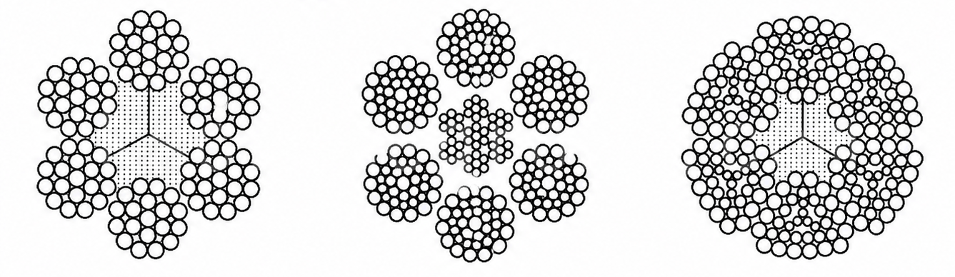
3Figure 2 Rotation resistant overhead crane wire rope selection example
Figure 2 Rotation-resistant wire rope example (Source: GB/T 8706-2017)
  1. Single-layer strand rope — A multi-strand rope consisting of one layer of strands laid helically around a core.
4Figure 3 Single layer multi strand rope example
Figure 3 Single-layer multi-strand rope example (Source: GB/T 8706-2017)
  1. Parallel-closed rope — A multi-strand rope consisting of two or more layers of strands laid in a single operation around a strand core or fibre core.
5Figure 4 Parallel closed rope example
Figure 4 Parallel-closed rope example (Source: GB/T 8706-2017)
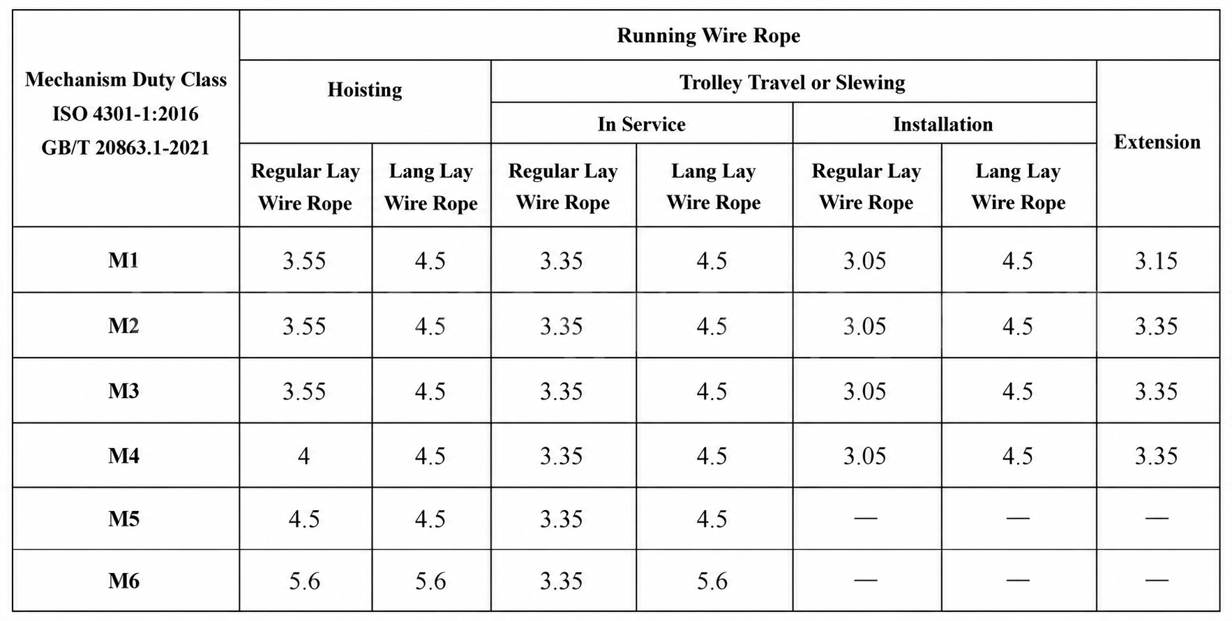
Table 2 Minimum safety factors for mobile cranes (Source: GB/T 34529-2017)

Mobile cranes include truck cranes, wheel-type cranes, crawler cranes, all-terrain cranes, and lorry-mounted cranes (GB/T 20776-2023).

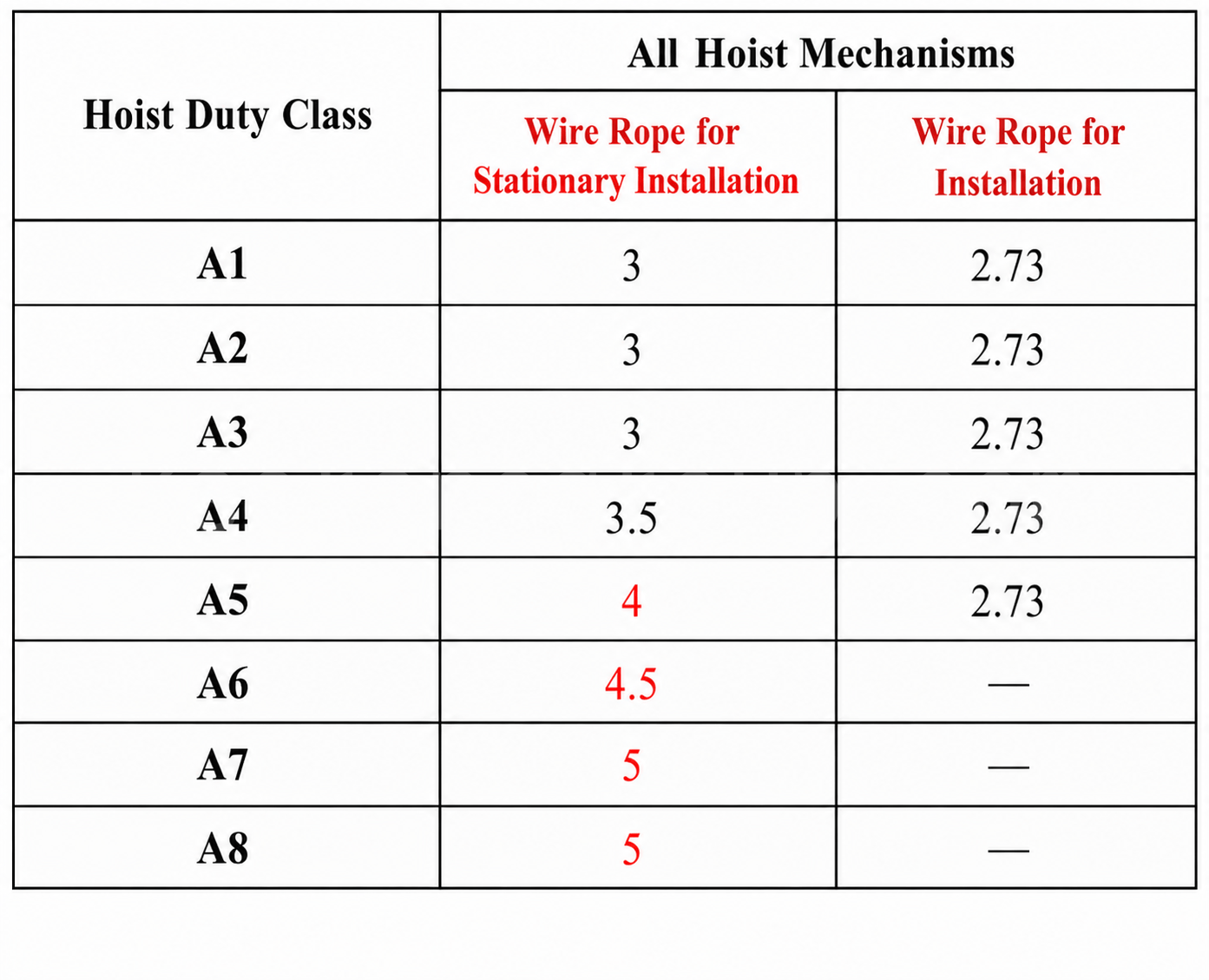
7able 3 Minimum safety factors for static ropes and erection ropes
Table 3 Minimum safety factors for static ropes and erection ropes (Source: GB/T 34529-2017)

3. Overhead Crane Wire Rope Selection

3.1 Minimum Breaking Force

Fmin ≥ S × Zp

SymbolMeaning
FminMinimum breaking force
SMaximum rope tension
ZpMinimum safety factor (see Tables 1, 2, 3)

Special handling for grab-bucket cranes:

ConditionClosing rope S_clHolding rope S_hold
Load auto-equalizedLoaded grab mass × 66% ÷ closing rope fallsLoaded grab mass × 66% ÷ holding rope falls
Load not auto-equalizedLoaded grab mass ÷ closing rope fallsLoaded grab mass × 66% ÷ holding rope falls

3.2 Maximum Fleet Angle

ConditionFleet angle limitReference
Rotation-resistant ropeGB/T 34529-2017, Clause B.4
Standard wire ropeGB/T 34529-2017, Clause B.4
Rope entering/exiting a sheave groove< GB/T 27546-2011, Clause 5.7.2; GB/T 3811-2008, Clause 6.3.3.3.1
Rope entering/exiting a grooved drum3.5°JB/T 9006-2013, Clause 4.7.2; GB/T 3811-2008, Clause 6.3.3.3.2
Plain drum, multi-layer, no spooling device1.7°JB/T 9006-2013, Clause 4.7.3; GB/T 3811-2008, Clause 6.3.3.3.3
For multi-layer drum winding, wire ropes with steel cores are recommended.
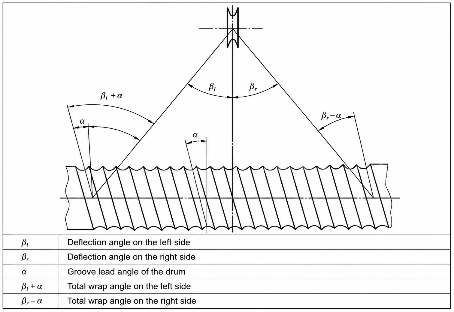
8Figure 5 Fleet angle and helix angle
Figure 5 Fleet angle and helix angle
SymbolMeaningLimit
αDrum helix angle
βleft + α, βright − αFleet angle relative to drum groove centreline≤ 3.5° (typically designed to max. 3.5°)
βleft, βrightFleet angle entering/exiting sheave< 5°

Measures to reduce fleet angle:

  • Increase drum diameter to reduce the winding range
  • Increase the distance between sheave and drum

3.3 Maximum Service Temperature for Wire Rope

Core typeMaximum temperatureNotes
Fibre core (FC)100°C
Steel core (IWRC) / single-strand rope / locked-coil rope200°CFrom 100°C to 200°C, a 10% strength loss may be assumed; special lubricant required above 100°C
Ambient temperature < −40°CStrength unaffectedNo working load reduction needed, but rope performance may depend on low-temperature lubricant effectiveness
If the operating environment prohibits wire rope lubrication, consultation between the supplier and purchaser is recommended, including inspection frequency requirements.

4. Overhead Crane Drum and Sheave Selection

4.1 Drum Type and Winding Direction

ComparisonPlain drumGrooved drum
RecommendationAcceptablePreferred (single-layer winding)
Multi-layer windingFlange height above outermost rope ≥ 0.5dSame as left

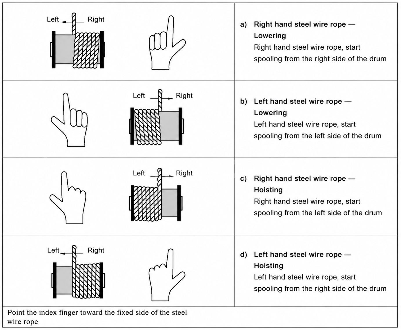
Winding direction rules:

  • Plain drum → The winding direction depends on the rope lay direction; determine the rope fixing point per Table 4.
  • Grooved drum → Either rope lay direction may be used, but the same lay as for a plain drum is preferred: left-hand helical groove matches right-hand lay rope, right-hand helical groove matches left-hand lay rope.
9Table 4 Correct method for determining the rope fixing point on a drum
Table 4 Correct method for determining the rope fixing point on a drum (Source: GB/T 34529-2017)

4.2 Groove Radius and Sheave Material

ParameterRecommended value
Groove radius0.525d–0.550d, optimum 0.5375d
Sheave included angle45°–60°

Sheave material selection guidelines:

Winding typeRecommended materialReason
Multi-layerPolymer sheaves or polymer-lined grooves acceptableThe most severe rope damage occurs at cross-over zones on the drum
Single-layerPolymer sheaves not recommendedDamage is primarily fatigue-induced; internal fatigue of the rope is harder to detect with polymer sheaves

For frequent service: use steel sheaves to increase the likelihood of external wear — this wear facilitates rope inspection. If polymer sheaves are used, it is recommended to include at least one steel sheave in the reeving arrangement, usually the one closest to the drum.

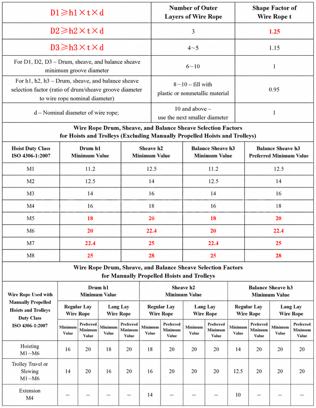
4.3 Minimum Drum and Sheave Diameter

10Table 5 Overhead Crane Drum and sheave selection coefficients and minimum diameter calculation
Table 5 Drum and sheave selection coefficients and minimum diameter calculation (Source: GB/T 34529-2017)

5. Special Operating Conditions

For molten metal handling, extremely severe and/or corrosive environments, and similar special conditions:

  1. The mechanism work duty shall not be lower than M5
  2. The Zp value shall be increased by 25%, up to a maximum of 9.0

The original document also covers the use of swivels and swivel joints, causes of wire rope deterioration, rope elongation and selection, and rope termination selection. Refer to the original standard for further study.

Reference standards(Query of Chinese Crane Standards):

  • GB/T 34529-2017 Cranes and hoists — Selection of wire ropes, drums and sheaves (IDT ISO 16625:2013)
  • GB/T 20118-2017 Steel wire ropes for general purposes (NEQ ISO 2408:2017)
  • GB/T 20863.1-2021 Cranes — Classification — Part 1: General (IDT ISO 4301-1:2016)
  • GB/T 6974.1-2008 Cranes — Vocabulary — Part 1: General (IDT ISO 4306-1:2007)
  • GB/T 5972-2023 Cranes — Wire ropes — Care and maintenance, inspection and discard (IDT ISO 4309:2017)
  • GB/T 8706-2017 Steel wire ropes — Vocabulary, designation and classification (MOD ISO 17893:2004)

Krystal
krystal
Crane OEM expert

With 8 years of experience in customizing lifting equipment, helped 10,000+ customers with their pre-sales questions and concerns, if you have any related needs, please feel free to contact me!

TAGS: Crane Design Standard,Crane Maintenance,Drum and Sheave,GB/T 34529,ISO 16625,overhead crane,Overhead Crane Wire Rope Selection,Rope Termination,Safety Factor,Wire Rope Hoist,Wire Rope Selection
English
Español Português do Brasil Русский Français Deutsch 日本語 한국어 العربية Italiano Nederlands Svenska Polski ไทย Türkçe हिन्दी Bahasa Indonesia Bahasa Melayu Tiếng Việt 简体中文 বাংলা فارسی Pilipino اردو Українська Čeština Беларуская мова Kiswahili Dansk Norsk Ελληνικά English